+8618060982349

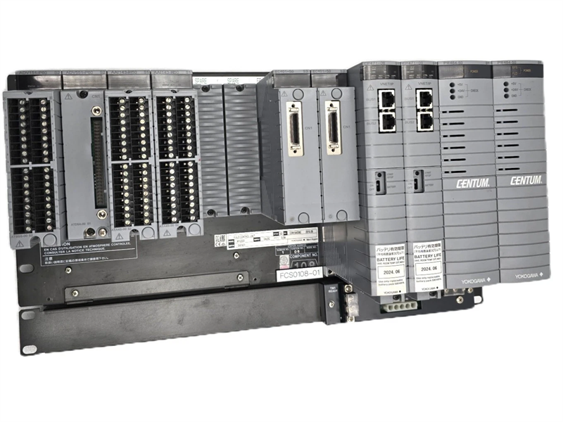
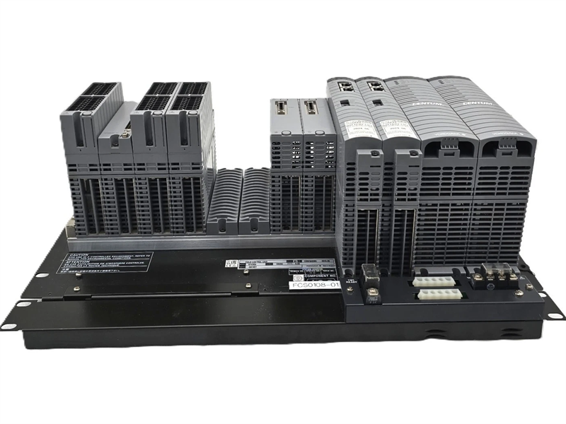
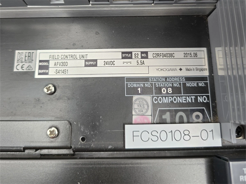
AFV30D-S41252 Yokogawa Duplexed Field Control Unit

AFV30D-S41252 Yokogawa Duplexed Field Control Unit (for Vnet/IP and FIO, 19-inch Rack Mountable)
  • Item NO.:

    AFV30D-S41252
  • Payment:

    T/T
  • Market Price:

    $20000
  • Product Origin:

    Japan
  • Shipping Port:

    Xiamen
  • Lead Time:

    5-7 days
  • Goods Stock:

    2
  • Product weight:

    8.0 kg

Manufacture
Yokogawa
Model
AFV30D-S41252
PN No.  AFV30D-S41252
Catalog
AFV30D
Description
ESB Bus Coupler Module
Origin Singapore
HS CODE 85389091
Dimension 15*13*5 (CM)
Weight 8.0 kg

Description:

The calculation formula is different between channels 1 to 8 and channels 9 to 16 of the SDV541 module; possibleESB Bus Coupler Module connects safety control units and safety node units via an ESB bus cable.For the installation specifications and the environmental conditions common to the systems, refer to “Integrated Production Control System CENTUM VP System Overview” (GS 33J01A10-01EN).

Processor
VR5532 (350 MHz)
Main Memory Capacity
128 MB
Memory Protection During Power Failure
Battery
Battery Back-up for Main Memory: Max. 72 hours
Battery Recharge Time: Min. 48 hours

READY Contact Output
2 terminals (NC, C)
Contact Points open during FCU failure
Contact Rating: 30 V DC, max. 0.3 A
Note: When option code /HKU is specified, a FCU fault contact is output from the House Keeping Unit (HKU).

Communication Interface
Vnet/IP Interface: Dual-redundant

For more details, refer to "Integrated Prodction Control Systrm CENTUM VP System Overview" (GS33J01A10-01EN)

HKU Interface (Option)
When option code /HKU is specified, a FCU fault contact is output from the HKU. Also, the environmental conditions of the cabinet connected via the HK bus and optical ESB bus can be monitored and the operating status of the HKU can be displayed on the HIS. System alarms can also be displayed.

No. of Node Units Connectable
Max. 13/FCU
The total number of ESB Bus Node Units (ANB10) and Optical ESB Bus Node Units (ANB11) that can be connected to FCU are 13 or less.

Module Configuration
Power Supply Module (PW481, PW482, or PW484):
2 modules for dual-redundant configuration Processor Module (CP461):
2 modules for dual-redundant configuration I/O Module (*1): Max. 8

*1: Non-standard component.


Installation Restrictions
To connect the ESB Bus Node Unit (ANB10) or Optical ESB Bus Node Unit (ANB11) to the FCU, install the ESB Bus Coupler Module (EC401 or EC402) in slots 7 and 8 of the FCU. For the dual-redundant configuration of the processor modules, EC401 or EC402 must be installed in both slot 7 and slot 8. In case ESB Bus has a single configuration, EC401 or EC402 must be installed in slot 7 and keep slot 8 empty.

To install the optical ESB bus node unit and ESB bus node unit in a remote location, use the Optical ESB Bus Repeater Master Module (ANT401 or ANT411) to connect them with an optical fiber cable. To install the optical ESB bus repeater master module in the FCU, install a pair of modules in slots 1 to 6 in order from right to left according to the number of branches. In a single configuration, install the individual modules in slots 1, 3, and 5 in order from right to left. For details, see the “Optical ESB Bus Repeater Module” (GS 33J60F51-01EN/GS 33J60F52-01EN).

For the limitations and precautions for installing I/O modules, see “FIO System Overview” (GS 33J60A10-01EN).

Power Supply
Voltage: 100-120 V AC, Frequency: 50/60 Hz
Voltage: 220-240 V AC, Frequency: 50/60 Hz
Voltage: 24 V DC
Specify with the Suffix Code.

Power Consumption
100-120 V AC: 200 VA
220-240 V AC: 230 VA
24 V DC: 5.5 A

Weight
Approx. 7.0 kg (AFV30S)
Approx. 8.0 kg (AFV30D)

Mounting
19-inch Rack Mounting:
Rack mount (M5x8 screws)
Insulation bush (accessory)

Connection
Power Supply: M4 screw terminal connection
Grounding: M4 screw terminal connection
READY Contact Output: M4 screw terminal connection

Network: Connect UTP cable (CAT5e or better) to Layer 2 switch.


Frequently Asked Questions:

1.Does the customer arrange for the inspection before the goods are shipped?
Confirmed acceppted this issue


2.What is the payment term?
Only wire transfer

3.When does the warranty period start?
One year from the time the client receives the goods.

Datasheet Link:

AFV30D-S41252 Yokogawa Duplexed Field Control Unit PDF Datasheet

AFV30D-S41252

Leave A Message
If you are interested in our products and want to know more details,please leave a message here,we will reply you as soon as we can.
Related Products
AAI835-S00
AAI835-S00 YOKOGAWA ANALOG INPUT/OUTPUT MODULE

AAI835-S00 YOKOGAWA ANALOG INPUT/OUTPUT MODULE

View More
EB401-10
EB401-10 YOKOGAWA ANALOG INPUT/OUTPUT MODULE

EB401-10 YOKOGAWA ANALOG INPUT/OUTPUT MODULE

View More
SAI533-H33
SAI533-H33 YOKOGAWA ANALOG INPUT/OUTPUT MODULE

SAI533-H33 YOKOGAWA ANALOG INPUT/OUTPUT MODULE

View More
SAI143-S33
SAI143-S33 YOKOGAWA ANALOG INPUT/OUTPUT MODULE

SAI143-S33 YOKOGAWA ANALOG INPUT/OUTPUT MODULE

View More
AAI543-S00
AAI543-S00 YOKOGAWA ANALOG INPUT/OUTPUT MODULE

AAI543-S00 YOKOGAWA ANALOG INPUT/OUTPUT MODULE

View More
AAI543-H00
AAI543-H00 YOKOGAWA Analog Output Module

 (4 to 20 mA, 16-channel, Isolated) AAI543-H00 YOKOGAWA 

ANALOG INPUT/OUTPUT MODULE

View More
ATB5S-00
ATB5S-00 YOKOGAWA ANALOG INPUT/OUTPUT MODULE

ATB5S-00 YOKOGAWA ANALOG INPUT/OUTPUT MODULE

View More
SDV144-S13
SDV144-S13 YOKOGAWA ANALOG INPUT/OUTPUT MODULE

SDV144-S13 YOKOGAWA ANALOG INPUT/OUTPUT MODULE

View More

click here to leave a message

Leave A Message
If you are interested in our products and want to know more details,please leave a message here,we will reply you as soon as we can.

Home

Products

about

contact