The following diagram shows the front view of the tachometer module and the rear view of several I/O modules.
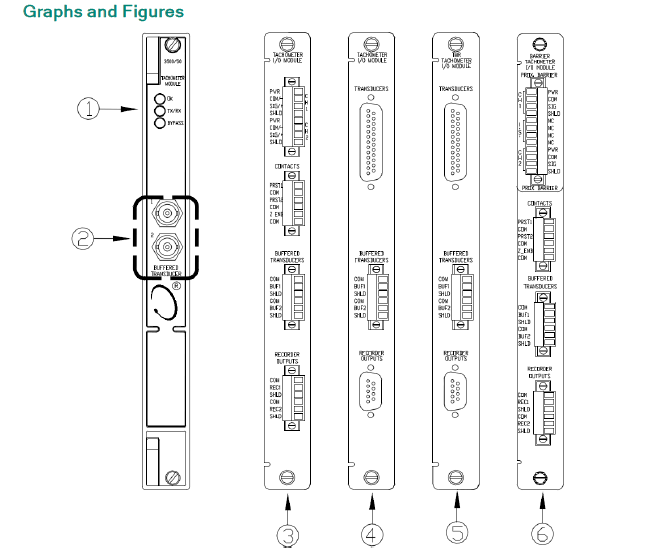
1.Status LEDs--133388-02
2.Buffered transducer outputs
3.I/O Module, Internal Terminations--133442-01
4.I/O Module, External Terminations--133434-01
5.I/O Module, TMR, External Terminations--133450-01
6.I/O Module, Internal Barrier, Internal Terminations--136703-01
10. 3500/53 Overspeed Detection Module
The Bentley Nevada 3500 Series Mechanical Inspection System's electronic overspeed detection system is a highly reliable, fast-response redundant tachometer system specifically designed for overspeed protection of machinery. The 3500/53 module can be used to form a 2-to-2 or 3-to-2 (recommended) voting system. The 3500 frame for installing the overspeed detection system requires a redundant power supply.
Each overspeed detection module receives a signal from an eddy current sensor or magnetic sensor, with an input signal range of +10.0V to -24.0V. Signals outside this range are limited within the module. Suitable for Bentley Nevada 3300 8mm eddy current sensor, 3300 16mm High Temperature Eddy Current Sensor (HTPS), 7200 5mm, 8mm, 11mm, and 14mm eddy current sensors, 3300 RAM eddy current sensor, or magnetic sensor.
Front Panel LED (Light Emitting Diode) Meanings:
OK LED: Indicates the 3500/53 module is working normally.
TX/RX (Transmit/Receive) LED: Indicates the 3500/53 module is communicating with other modules within the 3500 frame.
Bypass LED: Indicates the 3500/53 module is in bypass mode.
Test Mode LED: Indicates the 3500/53 module is in test mode.
Alarm LED: Indicates an alarm condition has occurred and the associated relay has actuated. Sensor Buffered Output: Each module has a coaxial connector on the front for buffered output. Each connector is short-circuit and electrostatic discharge protected. For speed, alarm levels (setpoints) can be set below or above. Additionally, a danger (overspeed) setpoint can be set for speed. All alarm setpoints are configured by software. Alarm points are adjustable and typically adjustable within the 0–100% full scale range. Alarm time delay: Less than 30ms at frequencies above 300 Hz. For other functions, please refer to the 3500/53 Overspeed Protection System Operation and Maintenance Manual.
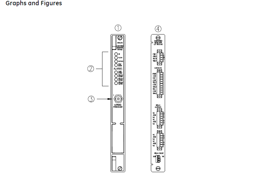
1) Main Module, front view.--133388-01
2) Status LEDs
3) Buffered transducer output. Provides an unfiltered output for the transducer. The output is short-circuit protected.
4) I/O Module, rear view.--133396-01
11.3500/32M 4-Channel Relay Module
The 4-Channel Relay Module is a full-height module that provides four relay outputs. Any number of 4-Channel Relay Modules can be placed in any of the slots to the right of the Transient Data Interface Module. Each output of the 4-Channel Relay Module can be independently programmed to perform voting logic.
Each relay utilized on the 4-Channel Relay Module includes Alarm Drive Logic.
Programming for the Alarm Drive Logic uses AND and OR logic, and can use alarming inputs (Alert and Danger statuses), Not- OK, or individual PPLs from any monitor channel or any combination of monitor channels in the rack. You can program this Alarm Drive to meet your application needs using the 3500 Rack Configuration Software.
Front Panel LED Meanings:
OK LED (Light Emitting Diode): Flashes when the module is working normally.
TX/RX LED: Used for transmission and reception; flashes when communication between this module and other modules in the frame is normal.
H ALARM LED: Flashes when the relay channel is in alarm state.
Relay Type: Two single-pole double-throw (SPDT) relays connected together to form a double-pole double-throw (DPDT) relay.
Sealing: Epoxy resin sealed; contact life 100,000 cycles @ 5A, 24Vdc or 120Vdc.
Operating Mode: Each channel can be selected by a switch to be normally de-energized or normally energized.
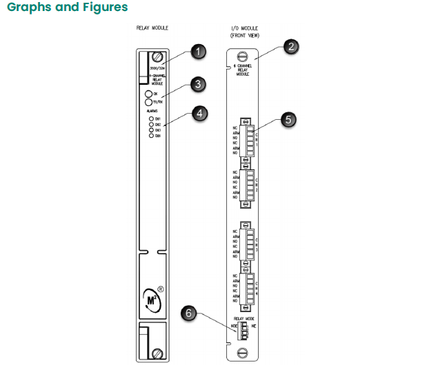
1.Relay module--149986-02
2.I/O module--125720-01
3.Status LEDs
4.Relay channel LEDs
5.Relay contacts
6.Relay mode selection switch
Address : Unit 1904, No.96-2 Lujiang Road, Siming District, Xiamen
Phone/WhatsApp/Skype : +86 18060982349
E-mail : sales6@nseauto.com