


|
Manufacture |
GE |
|
Model |
DS200PCCAG6ACB |
| PN No. |
DS200PCCAG6A |
|
Catalog |
EX2000 |
|
Description |
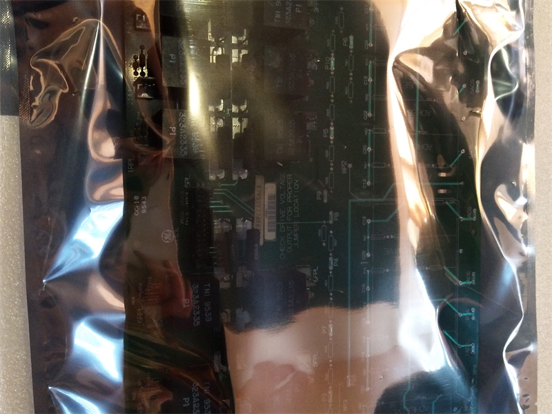
PCCA POWER CONNECT CARD
|
| Origin | USA;CN |
| HS CODE |
85389091 |
| Dimension |
28.2*15.2*4.19 (CM) |
| Weight | 0.8 kg |
Description:
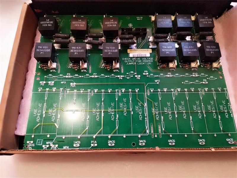
The DS200PCCA Power Connect Card (PCCA) provides an interface between the drive’s control circuitry and the SCR power bridge.
The PCCA board uses pulse transformers to provide gate drive to the SCR bridge. For low-to-medium horsepower controllers, the PCCA board also includes snubber circuits to control spikes across the ac lines, dc bus, and gate drivers. For higher horsepower controllers, some or all of the snubber circuits are omitted from the PCCA board, and are located elsewhere in the system.
BOARD GROUPS
The PCCA board has ten group numbers. The group number used in a system is determined by the system voltage, frame size, and whether the system uses regenerative or non-regenerative power conversion. Table 1 summarizes the applications of the various PCCA board group numbers.
The armature voltage scaling depends on which PCCA board group number is used:
• G1, G7, G9 – Regenerative, 240 – 630 volts
• G2, G8, G10 – Non-regenerative, 240 – 700 volts
The PCCA board has four wire jumpers, designated JP1, JP2, WP3, and WP4 that select system voltage and determine snubber capacitor connections.
APPLICATION DATA
BOARD HARDWARE
The PCCA board includes configurable jumpers and wiring plug connectors (there are no LEDs, fuses, testpoints, or switches) as part of the board. These items are described in the following paragraphs of this section.
CONFIGURABLE JUMPERS (JP and WP)
The PCCA board has four wire jumpers, designated JP1, JP2, WP3, and WP4.
Jumpers JP1 and JP2 must be connected to the appropriate stab terminals P3 through P10, as determined by the card group number and system voltage. Jumpers WP3 and WP4 are used to connect stab terminals P2A to P2B, and P1A to P1B, respectively. These jumpers are used to select whether the PCCA snubber capacitors are connected to the same point on the power bridge as the voltage feedback channel.
Figure 1 shows the layout of the PCCA board, including the locations of the stab terminals. Table 2 lists and defines the placement of the wire jumpers for various PCCA board group numbers and system voltages.
BOARD CONNECTORS
The PCCA board sends forward and reverse gate pulse signals to the SCR bridge via twelve plug connectors, 1RPL − 6RPL and 1FPL − 6FPL, and communicates with the power supply board via one additional plug connector, 5PL. See Figure 1 for an PCCA board layout diagram showing the locations of these connectors and see Tables 4 and 5 for the signal descriptions of the connectors.
Frequently Asked Questions:
1.Does the customer arrange for the inspection before the goods are shipped?
Confirmed acceppted this issue
2.What is the payment term?
Only wire transfer
3.When does the warranty period start?
One year from the time the client receives the goods
Datasheet Link:
 DS200PCCAG6ACB GE EX2100 PCCA POWER CONNECT CARD PDF Datasheet