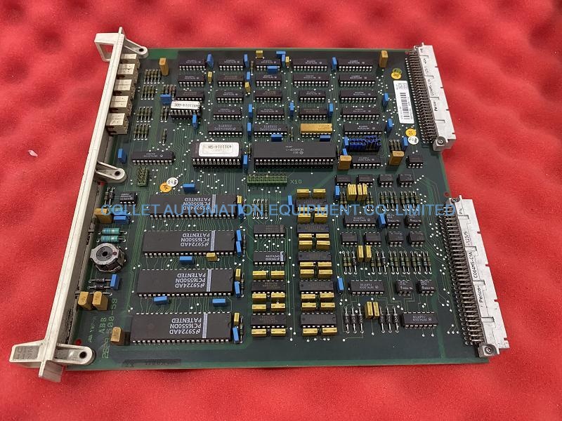



|
Manufacture |
ABB |
|
Model |
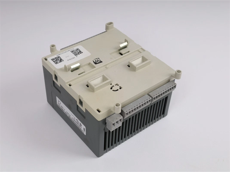
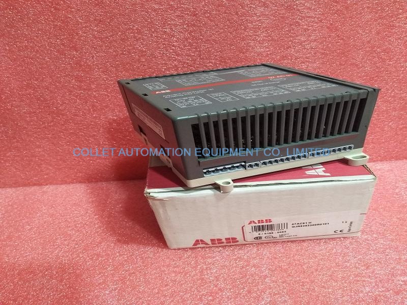
07 DI 92 |
| PN No. |
GJR5252400R0101 |
|
Catalog |
AC160 |
|
Description |
Redundant Processor Units |
| Origin | Sweden |
| HS CODE |
85044082 |
| Dimension |
28*21*14(CM) |
| Weight | 1.8 kg |
Description:
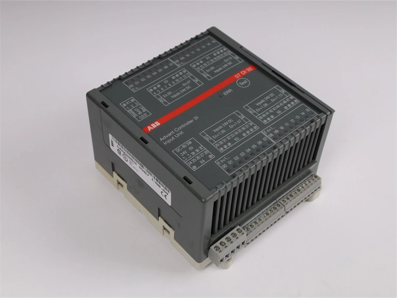
The digital input module 07 DI 92 is used as a remote module on the CS31 system bus. It contains 32 inputs, 24 V DC, in 4 groups with the following features:
• The 4 groups of the inputs are electrically isolated from each other and from the rest of the unit.
• The module occupies two digital addresses for inputs on the CS31 system bus.
The unit works with a supply voltage of 24 V DC.
The system bus connection is electrically isolated from the rest of the unit.
Display and operating elements on the front panel
1 32 green LEDs to indicate the signal status of the inputs
3 Red LED for error messages
4 Test button
Electrical connection
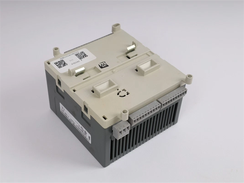
The module can be mounted on a DIN rail (15 mm high) or with 4 screws. The following illustration shows the electrical connection of the input module.
Addressing
An address must be set for each module to enable the basic unit to correctly access the inputs and outputs. A detailed description about "Addressing" can be found in the chapter "Addressing" of the basic units and couplers.
The address setting is accomplished with the DIL switch located under the slide cover on the right side of the module housing. When using basic units 07 KR 91, 07 KT 92 to 07 KT 97 as bus master, the following address assignments apply
Note:
Module 07 DI 92 reads the position of the address switch only during the initialization after the power was switched on, which means, that changes of the setting during operation will remain ineffective until the next initialization.
Input/output configuration
No configuration data are required for the 07 DI 92.
Normal operation
• The module automatically initializes after the power has been switched on. During that time, all LEDs are switched on.
• When the CS31 system bus does not run, LED 3 flashes
• The LED 3 goes out again after the system bus runs correctly and the unit does not detect any error.
• The 32 green LEDs 1 show the signal status of the 32 inputs.
Displays
By pressing the test button, an LED test is initiated. All LEDs must light up. Following that, the position of the address switch is displayed for about 3 seconds by LEDs 00 to 07 which was set by module 07 DI 92 during the initialization. In this case LED 00 shows the setting of switch 1 (LEDs 0...7 are assigned to switches 1...8 ).
Pharameters:
Permissible temperature range during operation 0...55 °C
Rated supply voltage 24 V DC
Nominal signal voltage at inputs V DC
Max. current consumption 0.15 A
Max. nominal load capacity for supply terminals 4.0 A
Max. power dissipation inside the unit 10 W
Protection against incorrect polarity of supply voltage yes
power supply max. 2.5 mm2
CS31 system bus max. 2.5 mm2
signal terminals max. 1.5 mm2
reference potentials ZP0, ZP1, ZP2, ZP3 max. 1.5 mm2
Number of inputs 32
Number of interfaces 1 CS31 system bus interface
Address setting Coding switch under the cover located on the right side of the housing
Operation and error displays a total of 33 LEDs
Frequently Asked Questions:
1.Does the customer arrange for the inspection before the goods are shipped?
Confirmed acceppted this issue
2.What is the payment term?
Only wire transfer
3.When does the warranty period start?
One year from the time the client receives the goods.
Datasheet Link:
 07 DI 92 ABB GJR5252400R0101 Digital Input Module PDF Datasheet