


|
Manufacture |
GE |
|
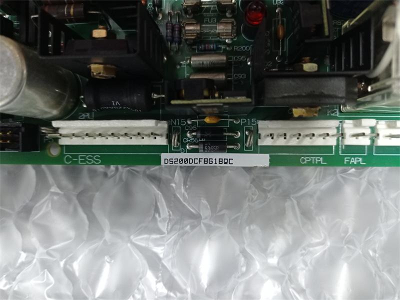
Model |
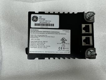
DS200DCFBG1B |
| PN No. |
DS200DCFBG1B |
|
Catalog |
EX2000 |
|
Description |
DC Power & Feedback Card |
| Origin |
United States (US) |
| HS CODE |
85389091 |
| Dimension |
28*16*8 (CM) |
| Weight | 0.7 kg |
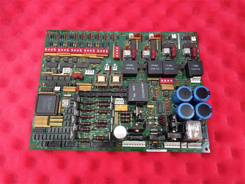
Description:
The DS200DCFB Power Supply Board (DCFB) receives 38 and 115 V ac (24 V dc) input power from the control power transformer (CPT), and provides control-level power to the drive and 115 V ac power (NA) to the enclosure fans. The DCFB board includes the following circuits:
- Control-level power supplies (+5, ±15, and ±24 V dc)
- Motor field power circuits (except the SCR module)
- Driver circuits for the motor field SCR gate pulse generators
- Circuits to monitor numerous ac line and dc motor signals, including:
- Motor field currents (NA)
- Ac line current
- Ac line voltage magnitude and phase sequence
The DCFB board receives 38 V ac (±10%) from the CPT (24 V dc). This voltage is full-wave rectified and filtered to produce the unregulated ±24 V dc outputs. The +24 V dc output is rated at 3 A and the –24 V dc output is rated at 1 A.
Regulators on the DCFB board derive ±15 V dc from the ±24 V dc supplies. The ±15 V dc outputs are each rated at 0.8 A, of which 0.25 A is available for external loading.
The DCFB board also generates a +5 V dc, 4 A output from the +24 V dc supply. The /PSEN signal on 2PL goes to a TTL low state when the +5 V dc supply is in regulation and the signal goes high if the +5 V dc supply goes out of regulation. When high, /PSEN generates a microprocessor reset on the Drive Control Card (SDCC/LDCC).
The DCFB board provides isolated +5 and ±15 V dc supplies to power the armature current feedback circuits.
The power supply outputs are protected against short circuits by fuses FU2 and FU3 (7 A, 2AG). Light-emitting diodes (LEDs) CR51 and CR55 provide blown fuse indication for these fuses. The 115 V ac output is protected by fuse FU1 (1/2 A, 2AG). Neon light LT1 provides blown fuse indication for FU1.
VOLTAGE AND CURRENT FEEDBACK VCO CIRCUITS
The DCFB board includes voltage-controlled oscillator (VCO) circuits that convert input voltages to frequency signals. Each VCO has a nominal output frequency of 250 kHz. The output frequency varies from 0 to 500 kHz, depending upon the input voltage. VCO outputs are sent to the SDCC/LDCC board through connector 1PL to provide feedback of the following:
· SCR bridge ac input voltage
· Output bridge voltage
· Motor voltage (NA)
· Millivolt signals from field shunts
· Millivolt signals from armature shunts
The output bridge VCO circuit provides feedback to the SDCC/LDCC board through connector 1PL, pin 13 (1PL- 13). DIP switch SW4 is used to scale the voltage applied to the circuit. A frequency-to-voltage reconstruction circuit provides a diagnostic signal for testpoint TP37 on the SDCC/LDCC board through 1PL-37. The diagnostic bridge voltage signal can be viewed using an ac-coupled oscilloscope. The second VCO provides feedback of the motor voltage to the SDCC/LDCC board through 1PL-39. DIP switch SW5 is used to scale the voltage applied to the circuit.
Two other VCO circuits provide feedback of the input voltage from a shunt. The VCO output frequency signals are sent to the SDCC/LDCC board through connector 1PL.
The DCFB board also includes two motor armature VCO circuits. The frequency output signals from these VCOs are sent to the SDCC/LDCC board through 1PL-8 and 1PL-10. These VCOs are at the potential of the armature bus and are fed by an isolator.
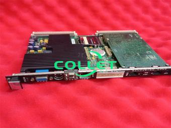
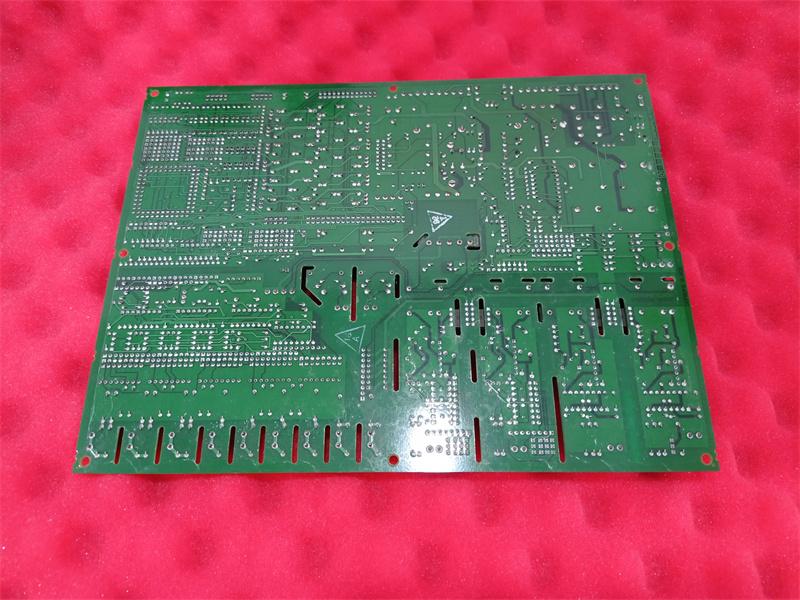
Physical and Installation
Board design:
- The printed circuit board (PCB) has a protective coating to adapt to industrial environments.
- Equipped with a multi-pin connector (such as AMP or Molex interface) for signal and power access.
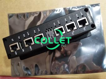
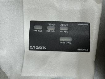
Indicator:
- PWR (power), RUN (operation), FAULT (fault) LED status indication.
Typical applications
Gas turbine fuel valve control: regulates gas flow to maintain combustion stability.
Steam turbine inlet valve positioning: achieves high-precision position control through LVDT feedback.
Variable frequency drive (VFD) interface: controls motor speed (such as lubricating oil pumps, cooling fans).
Frequently Asked Questions:
1.What's replacement of DS200DCFBG1B?
DS200DCFBG1C
2.What's the data sheet of DS200DCFBG1B?
GEI-1000028C
Data sheet Link:
 DS200DCFBG1B GE EX2000, DC Power & Feedback Card PDF Datasheet