


|
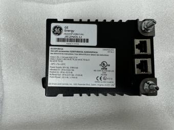
Manufacture |
GE |
|
Model |
IS200TBCIS2C |
| PN No. |
IS230TCISH6C |
|
Catalog |
MKVIES |
|
Description |
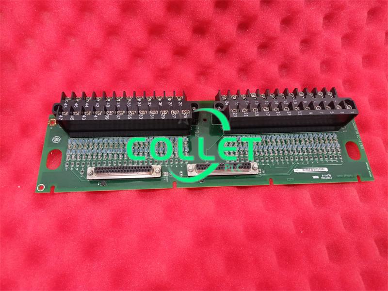
CONTACT INPUT BOARD |
| Origin |
United States (US) |
| HS CODE |
85389091 |
| Dimension |
28*16*8 (CM) |
| Weight | 1.0 kg |
Description:
The Analog Input Board (VAIC) accepts 20 analog inputs and controls four analog outputs. Ten inputs and two outputs are wired to each Analog Input Terminal board (TBAI). Inputs and outputs have noise suppression circuitry to protect against surge and high frequency noise. Cables connect the terminal board to the VME rack where the VAIC processor board is located.
The VAIC converts the inputs to digital values and transfers these over the VME backplane to the VCMI, and then to the controller. Input signals are fanned out to three VME board racks R, S, and T for TMR applications. The VAIC requires two terminal boards to monitor 20 inputs.
Three LEDs at the top of the VAIC front panel provide status information. The normal RUN condition is a flashing green, and FAIL is a solid red. The third LED is normally off but displays a steady orange if a diagnostic alarm condition exists in the board.
Each analog input has hardware limit checking based on preset (non-configurable) high and low levels set near the ends of the operating range. If this limit is exceeded a logic signal is set and the input is no longer scanned. If any one of the input’s hardware limits is set, it creates a composite diagnostic alarm, L3DIAG_VAIC, which refers to the entire board. Details of the individual diagnostics are available from the toolbox. The diagnostic signals can be individually latched, and then reset with the RESET_DIA signal.
Each input has system limit checking based on configurable high and low levels. These limits can be used to generate alarms, and can be configured for enable/disable, and as latching/nonlatching. RESET_SYS resets the out of limits. Details of the diagnostics are in GEH-6421D, Vol. I Mark VI System Guide, Chapter 8, Troubleshooting and Diagnostics.
The TBAI terminal board has its own ID device, which is interrogated by the I/O board. The board ID is coded into a read-only chip containing the terminal board serial number, board type, revision number, and the JR, JS, JT connector location
The DTAI board is a compact analog input terminal board, designed for DIN-rail mounting. The board has 10 analog inputs and two analog outputs, and connects to the VAIC processor board with a single 37-pin. This cable is identical to those used on the larger TBAI terminal board. The terminal boards can be stacked vertically on the DIN-rail to conserve cabinet space.
Two DTAI boards can be connected to the VAIC for a total of 20 analog inputs and four analog outputs. Only a Simplex version of the board is available.
The functions and on-board noise suppression are the same as those on the TBAI. High density Euro-Block type terminal blocks are permanently mounted to the board, with two screw connections for the ground connection (SCOM). An on-board ID chip identifies the board to the VAIC for system diagnostic purposes.
Physical and Installation
- Module design:
May be equipped with LED status indicators (power, communication, fault).
- Identification information:
Typical applications
- Gas turbine control
Flame detector status monitoring
- Steam turbine system
Pressure/temperature transmitter interface
- Power plant auxiliary machine control
Alarm contact input
Frequently Asked Questions:
1.What's replacement of IS200TBAIS1C?
IS200TBAIS2C
2.What's the data sheet of IS200TBAIS1C?
GEH-6421
Data sheet Link:
 IS200TBAIS1CED IS230TAISH2C GE MKVIES ANALOG I/O BOARD PDF Datasheet