


|
Manufacture |
GE |
|
Model |
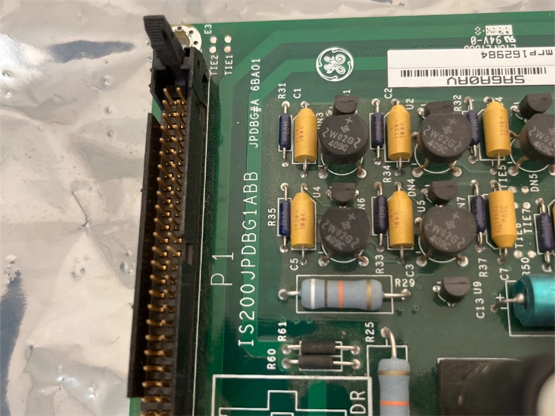
IS200JPDBG1A |
| PN No. |
IS200JPDBG1AAB |
|
Catalog |
MKVIe |
|
Description |
POWER DISTRIBUTION BOARD |
| Origin | U.S.A./CN |
| HS CODE |
85389091 |
| Dimension |
26.4*21.3*16 (CM) |
| Weight | 4.5kg |
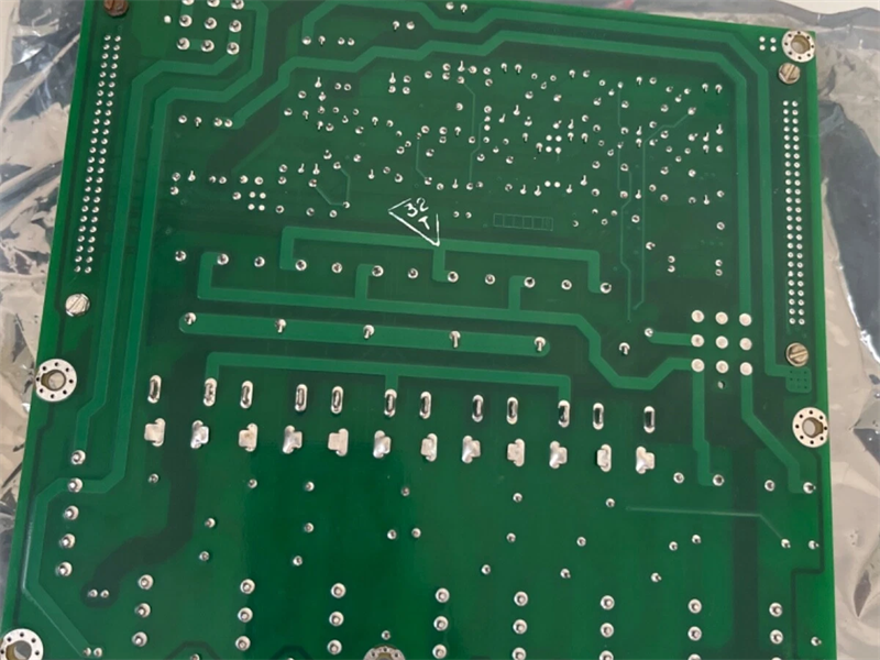
Description:
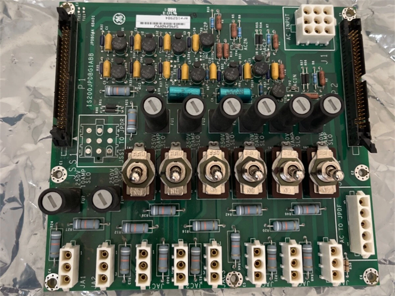
The ac Power Distribution (JPDB) board conditions, monitors, and distributes ac power. The module contains two line filters and a IS200JPDB circuit board. The module features two separate ac distribution circuits, each rated for 20 A at 115 or 230 V ac. The input circuits should be wired in parallel to avoid PPDA alarms when a single source of ac power is provided.
For each circuit, one fused, and three fused and switched branch circuit outputs are provided. Connection to an optional JPDF 125 V dc distribution module is provided. The IS200JPDB includes passive monitoring circuits for both ac magnitudes as well as status feedback for all fused circuits. The monitoring circuits are on connector P1, compatible with cable connection to a board containing a power diagnostic PPDA I/O pack. IS200JPDB also has a P2 connector for pass-through of monitoring signals from other power distribution system cards.
Two JPDB modules could be cabled into a single PPDA I/O pack when needed.
IS2020JPDBG2 provides an additional connector when an ac source selector is required in a system. The connector intercepts the two ac sources supplied to JPDB and routes them to the JSS1 connector on the board edge. Output of the ac selector is then wired to JSS1 and conducted to the individual branch circuit outputs.
Compatibility
The IS2020JPDB is compatible with the feedback signal P1 / P2 connectors on JPDE, JPDF, JPDS, and JPDM leading to a PPDA I/O pack. Connector JAF2 is compatible with the ac input on the JPDF module of the same name.
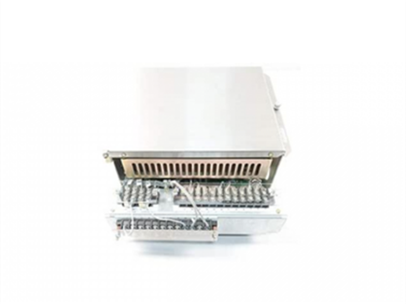
Installation
The IS2020JPDB module is base-mounted vertically on a metal back base in a cabinet used by the PDM. A connection must be made between the IS2020JPDB sheet metal and the system Protective Earth.
Input power is applied to terminals AC1H (line) and AC1N (neutral) for the first ac circuit, and AC2H (line) and AC2N (neutral) for the second ac circuit. Both ac inputs are required to have grounded neutral connections. Output circuits are connected as documented for the system.
If the power distribution system includes a PPDA power diagnostic I/O pack, a 50-pin ribbon cable is required from JPDB connector P1 to the P2 connector on the board holding PPDA. It is permissible for this connection to pass through other core PDM boards using the P2 connector.
Grounding
Mark* VIe systems divide ground into a protective earth (PE) and a functional earth (FE). The PE ground must be connected to an appropriate earth connection in accordance with all local standards. The minimum grounding must be capable of carrying 60 A for 60 seconds with no more that a 10 volt drop. The FE ground system must be bonded to the PE ground system at one point.
The JPDB is grounded through metal mounting supports fastened to the underlying sheet metal of a metal module. The ground is applied to the metal switch bodies on JPDB. Additionally, the ground is used as a local reference point when creating the feedback signals appearing on P2. The sheet metal of the module is insulated to the surface upon which it is mounted. This is done specifically to allow definition of the JPDB ground independent of the mounting surface. Typically, JPDB is mounted to a back base grounded to FE. JPDB would be located low in the cabinet and a separate ground wire from the JPDB module would be provided to PE. The minimum length of the ground wire is important to keep impedance low at radio frequencies, this allow the input line filters to function properly.
Physical Arrangement
When JPDB is used with an optional source, the selector should be positioned above the JPDB, thus allowing a short power connection between the two components using the JSS1 connector. When JPDB is used with a JPDF (125 V dc) board, the JAF1 connector provides ac power to JPDF. The best location for JPDF in this arrangement is below the JPDB, to minimize wiring lengths. The P1 and P2 ribbon cable headers on all of the JPDB boards are positioned, so the JPDS or JPDM holding the PPDA I/O pack is best located at the top of the board arrangement. This allows ribbon cables to flow from one card to the next, exiting the top, and entering the bottom of the next card until the PPDA host is reached. Connector P1 transmits feedback signals to a board hosting a PPDA I/O pack. Connector P2 receives feedback from other power distribution boards and passes the signals out of P1 to the PPDA.
Application Notes
When JPDB is used with a single ac input, the two ac inputs should be wired in parallel to the source. All output branch circuits are now live and there can be no diagnostics generated. If only one ac input is used, a diagnostic for loss of ac on the un-switched branch circuit can appear.
Operation
Two sources of ac power are wired to a terminal board on the right side of the JPDB module. The ac power goes to the ac line filter assemblies underneath the IS200JPDB circuit board. A wire harness connects the filter assemblies to the JPDB circuit board J1 connector.
The IS2020JPDBG01 module uses the IS200JPDBH1A circuit board. This board does not provide connection for an ac source selector and J1 ac power is wired directly to the output branch circuits.
The IS2020JPDBG02 module uses the IS200JPDBH2A circuit board. The board is designed for use with an ac source selector. It features the JSS1 connector mounted to the board. External filtered ac from connector J1 is fed to JSS1. The source selector output returns to the JSS1 to supply the branch circuit outputs.
JAF1 feeds power directly from input connector J1 to an adjacent optional JPDF board to power two DACA power conversion modules. The DACA modules convert the ac power to 125 V dc to be used as an ac backup for systems using a 125 V dc battery.
Features:
- High Reliability
Enhanced system stability and reliability through measures such as providing backup power and reducing EMI noise, ensuring normal operation even in harsh environments, exhibiting durability and stability.
- Modular Design
Facilitates installation and maintenance.
- Hot-Swap Functionality
Allows module replacement without interrupting system operation.
- Built-in Communication Functionality
Supports data transmission with the control system.
- Versatility
Applicable to all racks and terminal boards, facilitating integration and deployment in different systems, reducing user procurement and maintenance costs.
- Maintainability
Supports various maintenance and diagnostic functions, facilitating troubleshooting and repair, minimizing system downtime, and improving production efficiency.
Frequently Asked Questions:
1.What does Board Rating of IS200JPDBG1A?
115/230 V ac either circuit
50/60 Hz
30 A circuit breaker protection
2.What is the Total ac circuit loading of IS200JPDBG1A?
10 A on JAF1 AC1 plus 20 A total on JA1+JAC1+JAC3+JAC5
10 A on JAF1 AC2 plus 20 A total on JA2+JAC2+JAC4+JAC6
Datasheet Link:
 IS200JPDBG1AAB GE MKVIe Power Distribution (JPDB) Board PDF Datasheet