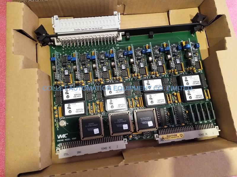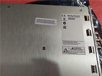



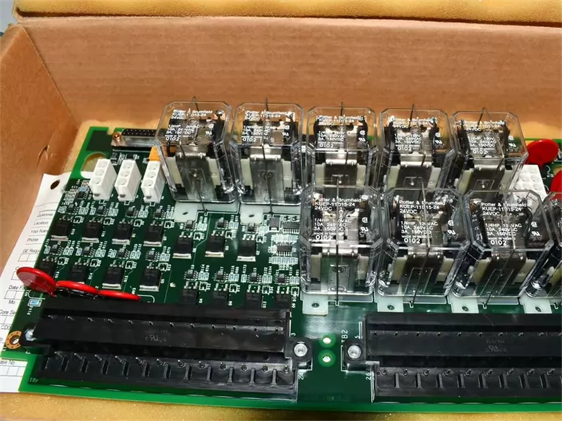
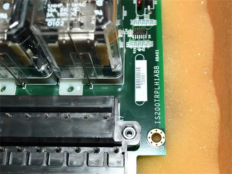
|
Manufacture |
GE |
|
Model |
IS200TRPLH1ABB |
| PN No. |
IS200TRPLH1ABB |
|
Catalog |
Mark VI |
|
Description |
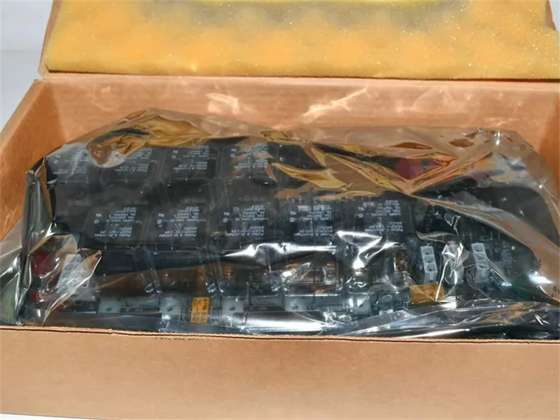
Turbine Primary terminal board
|
| Origin | USA |
| HS CODE |
85389091 |
| Dimension |
32*18*5 (CM) |
| Weight | 0.5 kg |
Description:
Functional Description
The Large Steam Turbine Primary Trip (TRPL) terminal board is used for the primary overspeed protection of large steam turbines. TRPL is controlled by the turbine Primary Turbine Protection controller (VTUR or PTUR), and contains nine magnetic relays in three voting circuits to interface with three trip solenoids (ETDs). TRPL works in conjunction with the TREL terminal board to form the primary and emergency sides of the interface to the ETDs. These two terminal boards are used in a similar way as TRPG and TREG are used on gas turbine applications.
Up to three trip solenoids can be connected between the TREL and TRPL terminal boards. TREL provides the positive side of the 125 V dc to the solenoids and TRPL provides the negative side. In addition, two manual emergency stop functions can be connected.
Mark VI Control Systems
In the Mark VI control system, the TRPL works with the VTUR board and only supports TMR systems applications. Cables with molded plugs connect TRPL to the VME rack where the VTUR board is located.
Mark VIe Control Systems
In the Mark VIe control system, the TRPL is controlled by the PTUR I/O packs on TTURH1C and only supports TMR applications. The I/O packs plug into the D-type connectors on TTURH1C, which is cabled to TRPL.
Operation
TRPL is used for TMR applications only. Three separate power buses, PwrA, PwrB, and PwrC for solenoid power, are brought in through connectors JP1, JP2, and JP3, and then distributed to TREL through connector J2.
The power buses have a nominal voltage of 125 V dc (70 to 145 V dc) or 24 V dc (18 to 32 V dc). The board includes power bus monitoring (three buses). The maximum current per bus is 3 A.
Each of the three trip solenoids is controlled by three relays using 2/3 contact voting.
The relay output rating (for 100,000 operations) is as follows:
• At 24 V dc, 3 A, L/R = 100 ms, with suppression
• At 125 V dc, 1.0 A, L/R = 100 ms, with suppression
The trip circuits include solenoid suppression, associated solenoid voltage monitoring, and trip relay contact monitoring. In the TRPL, the hardwired trip (E-Stop) and associated monitoring provides approximately 6.6 V dc to the I/O board when the K4 relays are picked up.
Diagnostics
The I/O controller runs the TRPx diagnostics. These include feedback from the trip solenoid relay driver and contact, solenoid voltage, and solenoid power bus. A diagnostic alarm is created if any one of the signals goes unhealthy (beyond limits). The Jx1 connectors on the terminal board have their own ID device, which is interrogated by the I/O board, and if a mismatch is encountered, a hardware incompatibility fault is created.
Frequently Asked Questions:
1.Does the customer arrange for the inspection before the goods are shipped?
Confirmed acceppted this issue
2.What is the payment term?
Only wire transfer
3.When does the warranty period start?
One year from the time the client receives the goods.
Datasheet Link:
 EC119 Vibration 922-119-000-003 cable assembly Cable Datasheet