


|
Manufacture |
GE |
|
Model |
IS230STAOH2A |
| PN No. |
IS230STAOH2A |
|
Catalog |
MKVIe |
|
Description |
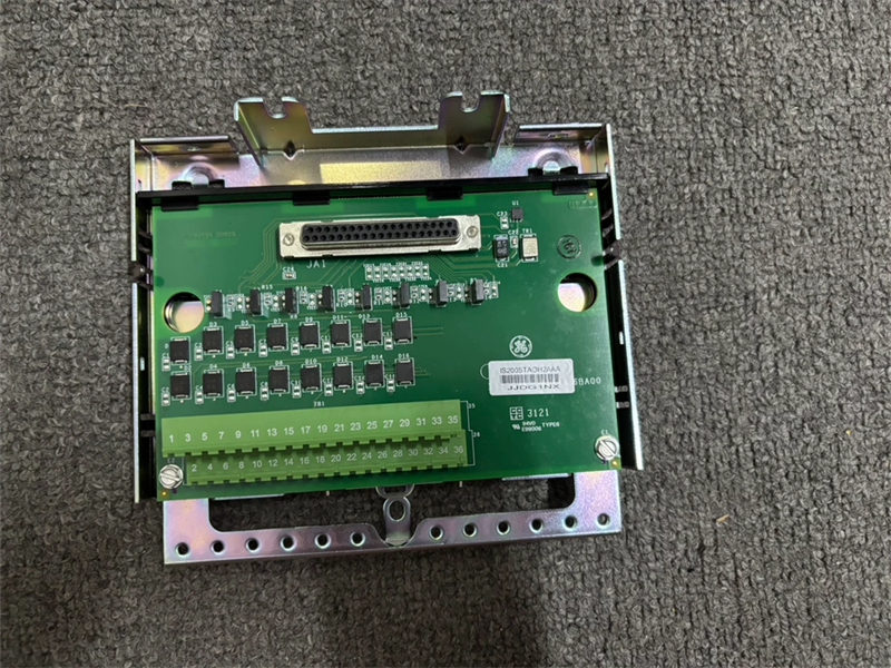
Analog Output Module
|
| Origin | USA |
| HS CODE |
85389091 |
| Dimension |
12.1*8.26*4.19 (CM) |
| Weight | 4.35 kg |
Description:
The Analog Output (PAOC) pack provides the electrical interface between one or two I/O Ethernet networks and an analog output terminal board. The pack contains a processor board common to all Mark* VIe distributed I/O packs and an acquisition board pair specific to the analog output function. The pack is capable of providing up to eight simplex 0-20 mA current loop outputs and includes an analog to digital converter for current feedback from each output.
Input to the pack is through dual RJ45 Ethernet connectors and a three-pin power input. Output is through a DC-37 pin connector that connects directly with the associated terminal board connector. Visual diagnostics are provided through indicator LEDs, and local diagnostic serial communications are possible through an infrared port.
Mark VI Systems
In the Mark* VI system, TBAI works with VAIC processor and supports simplex and TMR applications. One or two TBAIs can be connected to the VAIC. In TMR systems, TBAI is cabled to three VAIC boards.
To install the PAOC pack
1 Securely mount the desired terminal board.
2 Directly plug one PAOC I/O pack for simplex or three PAOC I/O packs for TMR into the terminal board connectors.
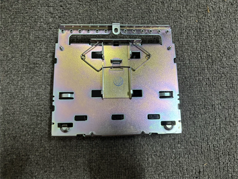
3 Mechanically secure the packs using the threaded studs adjacent to the Ethernet ports. The studs slide into a mounting bracket specific to the terminal board type. The bracket location should be adjusted such that there is no right-angle force applied to the DC-37 pin connector between the pack and the terminal board. The adjustment should only be required once in the life of the product.
4 Plug in one or two Ethernet cables depending on the system configuration. The pack will operate over either port. If dual connections are used, the standard practice is to connect ENET1 to the network associated with the R controller.
5 Apply power to the pack by plugging in the connector on the side of the pack. It is not necessary to insert this connector with the power removed from the cable as the I/O pack has inherent soft-start capability that controls current inrush on power application.
6 Configure the I/O pack as necessary.
Processor
The processor board in the pack is common to all Mark VIe Ethernet I/O packs. It contains the following:
• High-speed processor with RAM and flash memory
• Two fully independent 10/100 Ethernet ports with connectors
• Hardware watchdog timer and reset circuit
• Internal I/O pack temperature sensor
• Infrared serial communications port
• Status-indication LEDs
• Electronic ID and the ability to read IDs on other boards
• Substantial programmable logic supporting the acquisition board
• Input power connector with soft start/current limiter
• Local power supplies, including sequencing and monitoring
The processor board connects to an acquisition board specific to the I/O pack function. Upon application of input power, the soft-start circuit ramps up the voltage available on the processor board. The local power supplies are sequenced on, and the processor reset is removed. The processor completes self-test routines and then loads application code specific to the I/O pack type from flash memory. The application code reads board ID information to ensure the correct matching of application code, acquisition board, and terminal board. With a good match, the processor attempts to establish Ethernet communications, starting with request of a network address. The address request uses the industry standard dynamic host configuration protocol (DHCP) and the unique identification read from the terminal board. After Ethernet initialization, the processor programs the on-board logic, runs the application, and enables the acquisition board to begin operation.
Power Management
The I/O pack includes power management in the 28 V input circuit. The management function provides soft start to control current inrush during power application. After applying power, the circuit provides a fast current limit function to prevent a pack or terminal board failure from propagating back onto the 28 V power system. When power is present and working properly, the green PWR indicator will light. If the current limit function operates, the indicator will be out until the problem is cleared.
Frequently Asked Questions:
1.What is the IS230STAOH2A?
It is the MKVIe Analog Output developed by General Electric (GE).
2.What is the Number of channels of the IS230STAOH2A model?
Eight current output channels, single-ended (one side connected to common)
3.How To install the PAIC pack IS230STAOH2A?
Directly plug one PAIC I/O pack for simplex or three PAIC I/O packs for TMR into the terminal board connectors
Datasheet Link:
 IS230STAOH2A GE MKVIe Analog Output, Qty. 1 PAOC I/O I/O pack, DIN-rail mountPDF Datasheet