


|
Manufacture |
GE |
|
Model |
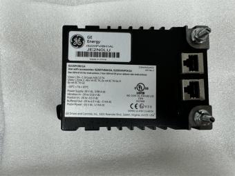
IS230TBAIH1C |
| PN No. |
IS230TBAIH1C |
|
Catalog |
MKVIe |
|
Description |
Analog I/O Module
|
| Origin | USA |
| HS CODE |
85389091 |
| Dimension |
12.1*8.26*4.19 (CM) |
| Weight | 4.35 kg |
Description:
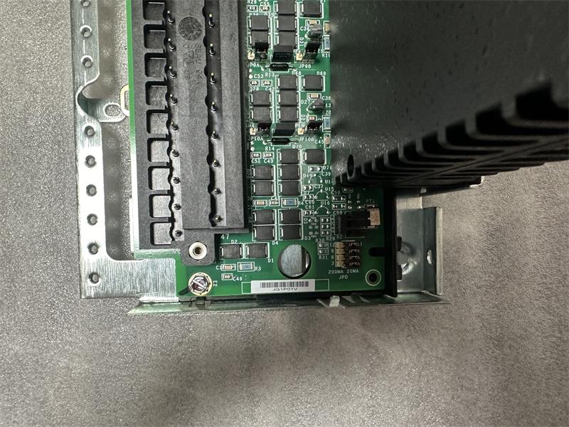
The Analog Input/Output (TBAI) terminal board supports 10 analog inputs and 2 outputs. The 10 analog inputs accommodate two-wire, three-wire, four-wire, or externally powered transmitters. The analog outputs can be set up for 0-20 mA or 0- 200 mA current. Inputs and outputs have noise suppression circuitry to protect against surge and high frequency noise.
TBAI has three DC-37 pin connectors provided on TBAI for connection to the I/O processors. Simplex applications are supported using a single connector (JR1). TMR applications are supported using all three connectors.
In TMR applications, the input signals are fanned to the three connectors for the R, S, and T controls. TMR outputs combine the current of the three connected output drivers and determine the total current with a measuring shunt. TBAI then presents the total current signal to the I/O processors for regulation to the commanded setpoint.
Mark VI Systems
In the Mark* VI system, TBAI works with VAIC processor and supports simplex and TMR applications. One or two TBAIs can be connected to the VAIC. In TMR systems, TBAI is cabled to three VAIC boards.
Installation
Connect the input and output wires directly to two I/O terminal blocks mounted on the terminal board. Each block is held down with two screws and has 24 terminals accepting up to #12 AWG wires. A shield terminal attachment point is located adjacent to each terminal block.
TBAI can accommodate the following analog I/O types:
• Analog input, two-wire transmitter
• Analog input, three-wire transmitter
• Analog input, four-wire transmitter
• Analog input, externally powered transmitter
• Analog input, voltage ±5 V, ±10 V dc
• Analog output, 0-20 mA
• Analog output, 0-200 mA
The processor board connects to an acquisition board specific to the I/O pack function. Upon application of input power, the soft-start circuit ramps up the voltage available on the processor board. The local power supplies are sequenced on, and the processor reset is removed. The processor completes self-test routines and then loads application code specific to the I/O pack type from flash memory. The application code reads board ID information to ensure the correct matching of application code, acquisition board, and terminal board. With a good match, the processor attempts to establish Ethernet communications, starting with request of a network address. The address request uses the industry standard dynamic host configuration protocol (DHCP) and the unique identification read from the terminal board. After Ethernet initialization, the processor programs the on-board logic, runs the application, and enables the acquisition board to begin operation.
Operation
TBAI provides a 24 V dc power source for all the transducers. The inputs can be configured as current or voltage inputs using jumpers (J#A and J#B). One of the two analog output circuits is 4-20 mA and the other can be configured as 4-20 mA or 0- 200 mA. The following table displays the analog I/O capacity of TBAI.、
Each 24 V dc power output is rated to deliver 21 mA continuously and is protected against operation into a short circuit. Transmitters/transducers can be powered by the 24 V dc source in the control system, or can be independently powered. Jumper JO selects the type of current output. Diagnostics monitor each output and a suicide relay in the I/O controller disconnects the corresponding output if a fault cannot be cleared by a command from the processor.
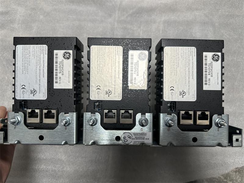
An industry-standard infrared serial communications port is provided on the processor board. Accessible through the pack front, this port provides diagnostic information on the pack status and an ability to program the pack when both Ethernet connections fail. It is possible to communicate with this port using most notebook computers and most hand-held Personal Digital Assistants (PDA).
Power Management
The I/O pack includes power management in the 28 V input circuit. The management function provides soft start to control current inrush during power application. After applying power, the circuit provides a fast current limit function to prevent a pack or terminal board failure from propagating back onto the 28 V power system. When power is present and working properly, the green PWR indicator will light. If the current limit function operates, the indicator will be out until the problem is cleared.
Frequently Asked Questions:
1.What is the IS230TBAIH1C?
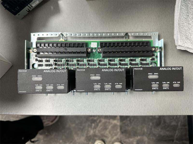
It is the MKVIe series Analog Input/Output (PAIC) pack developed by General Electric (GE).
2.What is the Number of channels of the IS230TBAIH1C model?
12 channels (10 AI, 2 AO)
3.How To install the PAIC pack IS230TBAIH1C?
Directly plug one PAIC I/O pack for simplex or three PAIC I/O packs for TMR into the terminal board connectors
Datasheet Link:
 IS230TBAIH1C GE MKVIe Analog I/O, Qty. 1 PAIC I/O I/O pack, DIN-rail mount PDF Datasheet