All the instrumentation and control systems used in the power station should be accurately connected to the ground. "Ground" is a common reference point site, which is defined by different names when applied in different situations. In the design of TSI cabinets, there are protective ground and signal ground to avoid noise interference. A correct grounding system can effectively suppress external interference, enhance the reliability of measuring instruments, and reduce factors such as interference generated by the system itself. It is an important guarantee for shielding technology. Poor grounding or inappropriate grounding points can cause significant electrical interference in the system, affecting its accuracy. Apart from the TSI cabinet, the TSI system of the steam turbine is a multi-point measurement system for large-scale equipment and structures. Therefore, it is even more necessary to avoid the formation of multi-point grounding to create a ground loop. During the system debugging process, each link needs to be inspected and tested before power-on debugging can be carried out.
Among the large-scale thermal power, combined cycle and nuclear power units supplied by Topteng Technology Trading Co.,Ltd, the commonly used monitoring instrument system brands are Bentley 3500 system, EPRO ATG6500 system and vibro-meter VM600 system. This article will briefly explain the grounding design and verification of the Vibrao-meter brand for users to refer to during debugging or troubleshooting. Please keep following this official account. We will further release relevant grounding requirements for other TSI brands in the future.
1.The signal input shielding terminal of the VM600MK1 system is grounded with the frame
If your company uses the MPC4/IOC4T MK1 series products of Vibrao-Meter, the resistance value between the Shield terminals of the six input signals of the IOC4T board and the frame housing is less than 1Ω. This work is tested before leaving the factory and can be retested during on-site debugging.
In addition, due to reasons such as raw materials, a production halt notice for this series of equipment has been officially issued. If your company has any spare parts requirements, please contact Topteng Technology Trading Co.,Ltd.
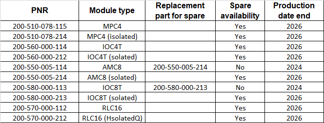
Note: This is only for display of our commonly used equipment. If you need to confirm more information about production suspension, please contact the supporting manufacturer or authorized dealer further.
2. The input signal of the MPC4/IOC4 MK2 monitoring and protection module is grounded separately
If your company uses the MPC4/IOC4MK2 series products of vibro-meter, then on the shielded terminal side of the cabinet input, the cabinet grounding copper bar is connected through the cabinet rail, and the resistance between them should be less than 1Ω. As shown by the red arrow in Figure 1.

Figure 1 Schematic diagram of the MPC4/IOC4 MK2 product being connected to the cabinet grounding copper bar through the cabinet rail
3. The VM600 frame housing is grounded
The grounding point of the VM600 system frame's casing is located at the grounding position at the power input terminal of the frame. As shown in Figure 2, at the position marked in red, where it is connected to the grounding copper bar of the TSI cabinet, the grounding resistance should be less than 1Ω. This work is tested before leaving the factory and then debugged and retested on site.
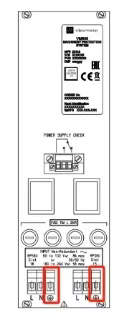
Figure 2 Grounding position of the frame shell
4. Grounding requirements during the installation and connection of sensors
1) Eddy current sensor
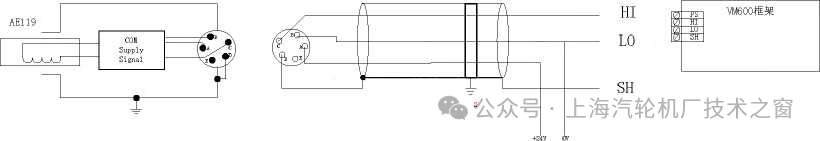
The eddy current sensor is mainly used for the measurement of signals such as relative vibration, shaft displacement, key phase, and differential expansion. The installation and electrical connection diagram is shown in Figure 3.
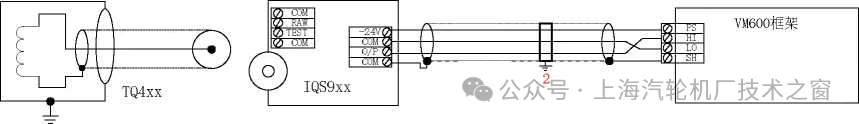
Figure 3 Schematic diagram of wiring and grounding of the eddy current sensor
Grounding requirements:
The housing of the eddy current sensor shares the ground with the machine housing through the installation bracket and does not require additional grounding.
The shielding layer of the connection cable from the COM terminal of the preamplifier IQS9xx to the VM600 frame should be connected to the shielding terminal of the signal input channel of the VM600 frame. A grounding bar should be set up at the entrance of the cabinet and grounding should be carried out here. The design institute needs to design a three-core shielded cable. During installation, it should be noted that the preamplifier needs to be installed in the terminal box through an insulating base plate.
A grounding bar is set at the incoming line of the TSI cabinet to ground the VM600 system frame.
2) Acceleration sensor
Large thermal power units use acceleration sensors to measure the absolute vibration of bearing housings, and their output signal is a two-wire current.
There are two usage methods for the acceleration sensor. One is that the output of the preamplifier is directly connected to the TSI frame via a cable for measuring the absolute vibration on the turbine side, as shown in Figure 4. Another type of preamplifier output is then connected to the TSI frame after passing through the isolation grid for the measurement of absolute vibration on the generator side, as shown in Figure 5.
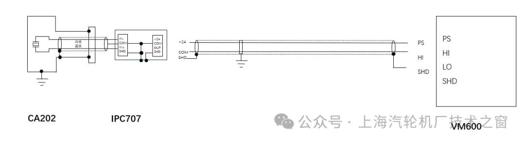
Figure 4 Schematic diagram of wiring and grounding of the acceleration sensor without isolation grid
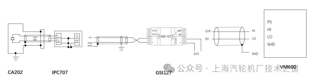
Figure 5 Schematic diagram of wiring and grounding of the acceleration sensor with isolation grid
Grounding requirements:
Probe side: The probe housing is grounded with the machine surface through installation bolts and no additional grounding is required.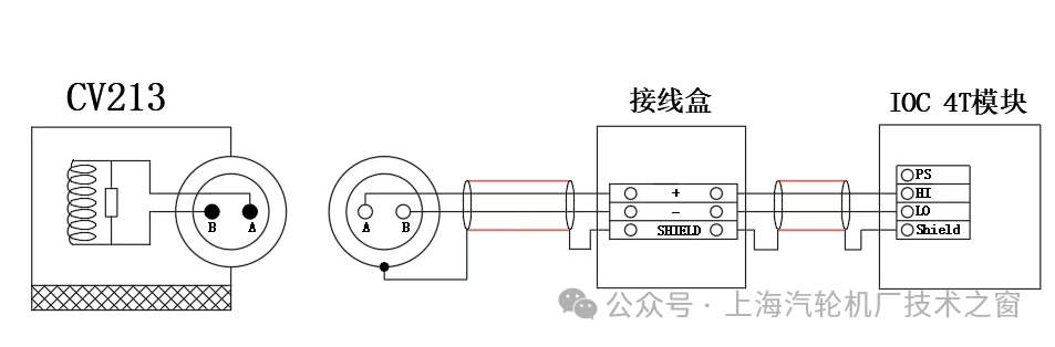


Address : Unit 1904, No.96-2 Lujiang Road, Siming District, Xiamen
Phone/WhatsApp/Skype : +86 18060982349
E-mail : sales6@nseauto.com