Speed is a very important parameter that indicates the operation of rotating equipment, especially the critical speed of rotating equipment, which is the speed at which the vibration frequency of the system resonates with the natural frequency of the rotating equipment. After the steam turbine is unloaded, the speed is prone to soaring. The premise for avoiding critical speed and soaring is that the speed measurement must be accurate and reliable. There are generally many means of speed measurement, such as centrifugal (tachometer), magnetoelectric induction, Hall, eddy current, photoelectric, etc. The two types of speed measurement used for steam turbines are mainly magnetoelectric induction and Hall.
1.1 Magnetoelectric induction sensor
The basic principle of magnetoelectric induction sensor is electromagnetic induction, which can be divided into constant magnetic flux type and variable magnetic flux (reluctance) type. The latter is widely used to detect the rotation speed of magnetic gears, impellers, perforated discs, etc. The sensor is encapsulated with a permanent magnet and a coil, forming a magnetic field in front of the sensor. When the gear disk rotates, the ferromagnetic teeth will cause the periodic change of the coil magnetic flux, thereby inducing an alternating amplitude electromotive force, the frequency of which is related to the number of gear teeth and the rotation speed:
n=60 f/Z
(n—measured speed; Z—number of gear teeth; f—frequency of induced electromotive force) When the number of gear teeth is 60, the speed n is the frequency f of the induced electromotive force. Factors affecting the induced electromotive force include: surface speed of the gear plate, size and spacing of the sensor and gear plate, and impedance of the measurement circuit. When the measurement object and detection circuit are determined, the higher the speed, the greater the induced electromotive force; the smaller the gap between the sensor and the gear, the greater the induced electromotive force.
In a certain project, the back-pressure steam turbine driving the circulating water pump uses the Zhejiang University Central Control DCS and its steam turbine control dedicated module to realize the steam turbine overspeed protection (OPS), and the speed measurement cycle can reach 20 ms. The dedicated module receives the speed signals of 3 sets of variable flux sensors on site, and simultaneously receives the two DI dry contact signals of switch tripping and emergency stop, and then issues a fast and reliable steam turbine overspeed alarm signal, and drives the overspeed protection solenoid valve through the relay output to realize the steam turbine overspeed protection function. It should be noted that the steam turbine control dedicated module must be used in conjunction with a specific main control card.
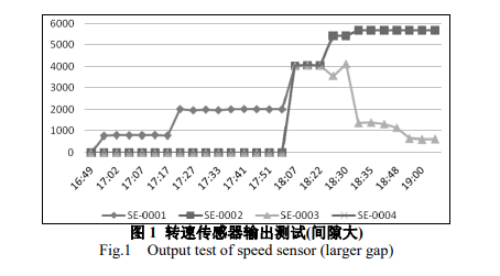
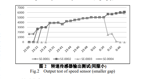
The steam turbine speed measurement module is actually also a pulse input module, but the detected signal amplitude is larger than that of the ordinary pulse module, the speed measurement cycle is shorter, and the accuracy is higher. The variable flux sensor signal is received through the ordinary pulse module. When the speed probe, gear plate and test loop impedance are completely consistent, the probe (SE-0002~0004) is rotated half a turn inward to reduce the gap with the gear plate. The results before and after adjustment are shown in Figures 1 and 2 respectively. The comparative analysis is as follows:
In the low-speed range, the three probes (SE-0002~0004) have no data. After the speed increases, the speed can be measured gradually. It is speculated that the surface speed is too low at low speed, and the induced electromotive force is always lower than the lower limit of the high-level signal domain after filtering and amplification, and the signal frequency cannot be distinguished;
In the medium-speed range, the data of the three probes are similar to the data measured by the 505 speed control system (SE-0001), which verifies that the output signal of the variable flux sensor has a frequency characteristic based on the speed;
In the high-speed range, some probe output signals show an obvious distortion trend. It is speculated that the coil induced electromotive force is always close to or higher than the lower limit of the high-level signal domain after filtering and amplification at high speed, making it difficult to distinguish the signal frequency.
1.2 Hall sensor
After the turbine has finished idling after tripping, the steam accumulated in the cylinder makes the temperature of the upper cylinder higher than that of the lower cylinder, causing uneven heating of the rotor. By turning the rotor continuously at a certain speed, thermal bending of the rotor can be avoided. Some turning clutch structures require that the rotor be completely stopped before turning, so it is necessary to set a zero speed measurement (the concept of zero speed is not only an absolute zero speed, but also an indication of operation below the minimum rotation speed). At the same time, zero speed can also assist in judging whether the turning is working properly. So, how to measure zero speed? Hall sensors can do it.
Hall sensors are sensors that use the Hall effect to convert measured physical quantities into electromotive force. When a semiconductor wafer is placed in a magnetic field with an induction intensity of B and a current I is passed through both ends of the wafer, an electromotive force will be generated in a direction perpendicular to the current and magnetic field . This phenomenon is the Hall effect. The magnitude of the electromotive force is U=KIB , where K is the Hall sensitivity coefficient, which is determined by the material and thickness of the semiconductor wafer. It can be seen that the Hall potential is independent of speed. Generally, a stable magnetic field is formed by the permanent magnets embedded in the teeth of the gear plate. The slight rotation of the gear plate can be detected by the presence or absence of the Hall potential. The general control system also has a certain allowable fluctuation range for the sensor signal, so the current stability requirements in the Hall element are relatively low. Of course, the distance between the sensor and the gear plate directly reflects the magnetic field strength, which is also a point that needs to be paid attention to during installation.
The relationship between the speed and frequency measured by the Hall sensor is consistent with that of the magnetoelectric induction sensor, which will not be repeated here. Hall sensors can also be used to measure vibration and displacement.
In summary, the variable flux (reluctance) type does not require an external power supply, but is not suitable for low-speed ranges. For example, the input module of the 505 controller cannot measure the speed when the sensor output voltage is less than 1Vrms (effective voltage). The Hall sensor can measure zero speed and has strong anti-interference ability, but it requires an external power supply and requires that the gear plate must have a permanent magnet of similar strength.
2 Speed Control
Steam turbine speed control is closely related to load control and is relatively complex, but the technology is now very mature and can generally be achieved through dedicated controllers, such as Woodward's 505/505E controller (9907-162) and Peak150 controller; large units (such as generator sets) can also be achieved through the integrated steam turbine digital electro-hydraulic control system (DEH), in which speed and load control are one of the most important parts of the DEH system; if the steam turbine is used to drive a large compressor unit with higher safety requirements, it can be achieved through the turbine compressor unit integrated control system (ITCC), such as CCC's Vanguard system, TRICON's TS3000 system, RockWell's T6300 Trusted system (formerly ICS Triplex), which can achieve dual or triple redundant control, and the integrated functions are more powerful and complex.
3 Steam turbine protection system
Serious over-limit of certain parameters of steam turbine may cause equipment damage or even machine destruction. Among them, steam turbine overspeed is the most harmful. Therefore, steam turbine overspeed may have multiple protection measures such as overspeed protection and emergency tripping. The interlocking of other important parameters is implemented through the emergency tripping system to implement emergency shutdown.
3.1 Steam turbine overspeed protection system
3.1.1 Electronic overspeed protection
To ensure the high reliability of steam turbine overspeed protection, three independent speed sensors and three independent detection modules (channels) are generally used to achieve a 2-out-of-3 redundant fault-tolerant effect. When two or more groups of speed signals are detected to be over-limit, a shutdown signal is immediately sent to the emergency trip system. The 2-out-of-3 redundant fault-tolerant structure also helps to find faults. If any group of signals is abnormal, maintenance can be arranged in a timely and orderly manner.
3.1.2 Mechanical overspeed protection
The mechanical overspeed protection of the steam turbine is achieved through centrifugal force. When the speed increases, the centrifugal force acting on the flyweight (or fly ring) of the emergency trip device increases until it is enough to break away from the preload spring force and fly out, hitting the emergency trip device and shutting down the steam turbine. This method of using mechanical centrifugal force to achieve overspeed protection shutdown is not necessarily very accurate. For example, the mechanical trip speed setting value of a small and medium-sized steam turbine in a certain project is 6180~6294rpm. In two overspeed protection tests, the measured data were 6137 rpm and 6129rpm respectively.
In the continuous development of steam turbines, the reliability of electronic overspeed protection has been technically proven, such as Woodward's Protech GII protector. Some steam turbine plants only set up GII electronic overspeed protection instead of mechanical overspeed protection.

3.2 Steam turbine electronic protection system
In addition to electronic overspeed protection, the electronic protection conditions of steam turbine units are generally set up with large bearing vibration, large axial displacement, high bearing temperature, low lubricating oil pressure, emergency stop button on site or in the control room, etc. On units with different purposes, there may be high lubricating oil temperature, low oil level in the oil tank, high exhaust pressure, high exhaust temperature and other protection conditions. When the measured parameters exceed the limit, an alarm and shutdown signal are issued [8], and the solenoid valve is activated to cut off the steam supply to the unit.
The electronic protection function is realized by DCS and has been successfully applied in small steam turbine units. It is relatively economical. However, this needs to be achieved by setting DCS card parameters and shortening the scanning cycle. The shorter the scanning cycle, the higher the load on the controller.
Large units or units with higher safety requirements generally use turbine safety monitoring and protection systems (TSI, or mechanical monitoring and protection systems MMS) and cooperate with ESD to achieve it. Commonly used TSI equipment currently include the 3300 series and 3500 series(3500/22M) of Bently (now part of GE Energy Group) in the United States, the EPRO MMS6000 series(A6500-UM) of Epro (formerly Philips) in Germany, and the VM600 series(MPC4) of Vibro-Meter in Switzerland.
3.3 Steam turbine emergency shutdown system
The steam turbine emergency shutdown system is a system that connects the electronic protection, overspeed protection system and shutdown solenoid valve. All shutdown signals generated by the steam turbine shutdown command, overspeed protection system, electronic protection system, shutdown button, etc., are shut down through the steam turbine shutdown solenoid valve to shut down the unit operation.

4 Conclusion
After understanding the principles of turbine speed, vibration and displacement measurement, it is not difficult to determine a reliable design solution. However, the control and safety protection system is closely related to the scale, application conditions and safety level requirements of the turbine unit, and a trade-off needs to be made between economy and reliability. In addition to the turbine, the automatic control part of other rotating equipment is also relevant. Understanding the characteristics of the equipment is helpful to the automatic control design work to a certain extent.
Address : Unit 1904, No.96-2 Lujiang Road, Siming District, Xiamen
Phone/WhatsApp/Skype : +86 18060982349
E-mail : sales6@nseauto.com