


|
Manufacture |
GE |
|
Model |
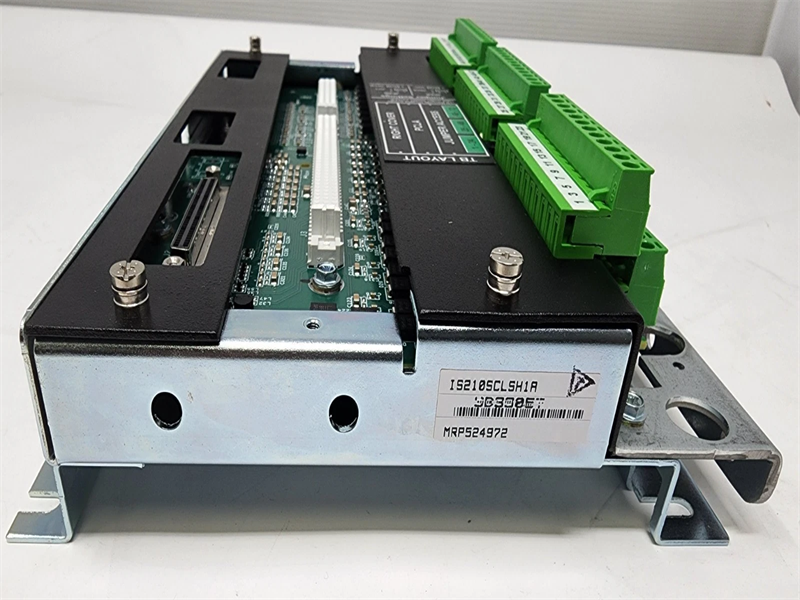
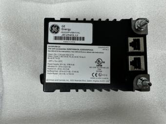
IS210SCLSH1A |
| PN No. |
IS210SCLSH1A |
|
Catalog |
MKVIe |
|
Description |
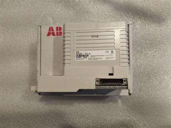
CORE ANALOG Terminal Board
|
| Origin | USA |
| HS CODE |
85389091 |
| Dimension |
16.8*15*5.5 (CM) |
| Weight | 1.327 kg |
Description:
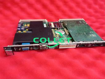
The Core Analog I/O for Aero-derivative gas turbines (PCLA) and associated Core Analog (SCLS and SCLT) terminal boards provide a large portion of the analog signal I/O required to operate an engine. PCLA and SCLT provide thermocouple inputs, RTD inputs, voltage inputs, and 4-20 mA current loop inputs and outputs. PCLA can be applied in simplex controller simplex I/O, dual controller simplex I/O, dual controller TMR I/O and TMR controller TMR I/O control systems. A single SCLT terminal board fans signal inputs to one or three connected PCLA(s).
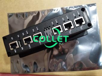
PCLA provides the electrical interface between one or two Ethernet I/O networks and the terminal board. It contains a processor board common to all Mark VIe distributed I/O. Input to the PCLA module is through dual RJ-45 Ethernet connectors and a 28 V dc power connector P1.
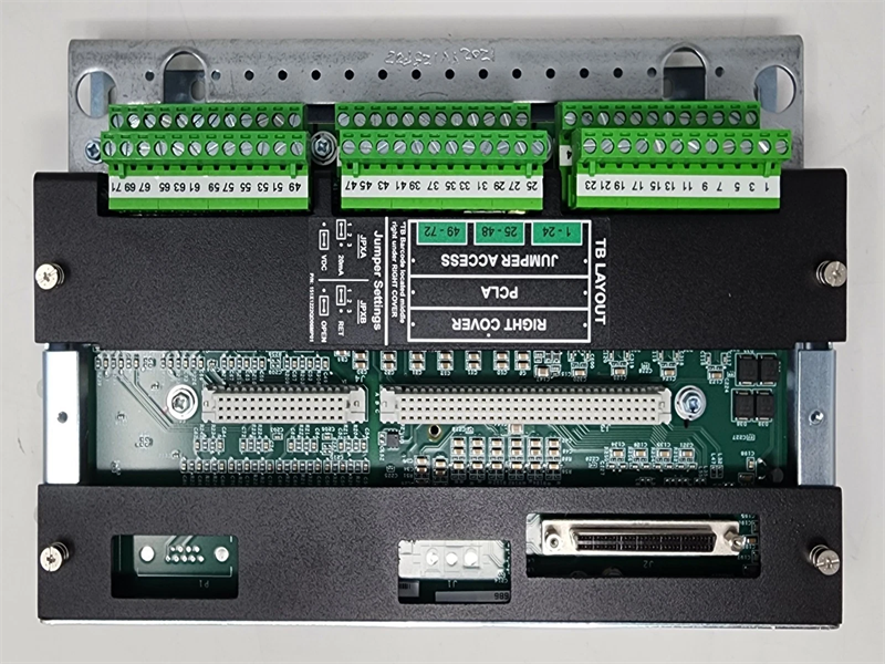
Field device I/O is connected through 72 Euro-style box terminals on the SCLS edge and is connected through 48 Euro-style box terminals on the SCLT edge. Connection to SCLS is through 96-pin J3 and 48-pin J4 connectors on SCLS. The connection between SCLS and SCLT is through one 68-pin cable on the J2 connector on SCLS, and the JR/JS/JT connector on SCLT.

How to install the PCLA module?
1. Securely mount the SCLS board with the help of four mounting holes at the four corners.
2. Directly plug the PCLA into the terminal board connectors J3 and J4.
3. Mechanically secure the pack using two-side mounting holes.
4. If SCLT is the part of configuration then the SCLT and a plastic insulator mount on a sheet metal carrier that then mounts on a DIN-rail. Optionally, the SCLT and plastic insulator mounts on a sheet metal assembly and then bolts directly to a cabinet.
5. Connect the SCLS to an optional associated SCLT terminal board using one 68-pin cable. The connection between SCLS and SCLT is through one 68-pin cable on the J2 connector on SCLS and the JR/JS/JT connector on SCLT.
6. If using a simplex configuration, connect the JR connector on SCLT to the J2 connector on SCLS through the 68-pin cable. If using a TMR configuration, connectors on SCLT are paired by a network connection. For example, JR1 connects to the SCLS-PCLA through the R controller network, JS connects to the SCLS-PCLA through the S controller, and JT connects to the SCLS-PCLA through the T controller. It is important to fully seat the cable mounting screws, finger-tight only, into PCLA and SCLT to ensure proper cable grounding. Failure to secure the cables may result in an inability of PCLA to read the electronic ID on SCLT and may reduce the quality of other signals.
Note When removing 68-pin cables, ensure that the hex posts in the board-mounted connectors do not turn when backing out the cable thumbscrews.
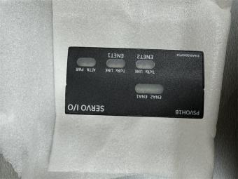
7. Plug in one or two Ethernet cables depending on the system configuration. When a single IONet connection is used, the module operates correctly over either port. If dual connections are used, standard practice is to hook ENET1 to the network associated with the R controller. However, the PCLA is not sensitive to Ethernet connections, and negotiates proper operation over either port. If TMR PCLA modules are present, the network connection should match with the connection made to the SCLT. For example, the PCLA module with R IONet connection should have cables that go to the SCLT JR connector.
8. Check grounding of the SCLS/SCLT shield wire terminals. In most applications, shield ground terminals are electrically tied to the sheet metal the board is mounted on. The mounting then supplies the ground path for the terminals.
9. Apply power to the module through the P1 connector on PCLA and check the power and Ethernet status indicator lights.
10. Use the ToolboxST* application to configure the PCLA as necessary. See also the Auto-Reconfiguration section.
PROCESS
The processor board is common to all Mark VIe Ethernet I/O packs or modules. It contains the following:
• High-speed processor with RAM and flash memory
• Two fully independent 10/100 Ethernet ports with connectors
• Hardware watchdog timer and reset circuit
• Internal temperature sensor
• Status-indication LEDs
• Electronic ID and the ability to read IDs on other boards
• Input power connector with soft start/current limiter
• Local power supplies, including sequencing and monitoring
Frequently Asked Questions:
1.What is the IS210SCLSH1A?
It is the MKVIe CORE ANALOG Terminal Board by General Electric (GE).
2.What is the Processor of the IS210SCLSH1A model?
SCLS has 8 thermocouples, 4 analog inputs, 8 RTDs, 1 current output
3.How To install the VME Board IS210SCLSH1A?
Directly plug the PCLA into the terminal board connectors J3 and J4.
Datasheet Link:
 IS210SCLSH1A GE MARK VIe CORE ANALOG Terminal Board PDF Datasheet