System overview
The VM600 machinery protection system (MPS) is a digital machinery protection system designed for use in industrial applications. It is intended primarily for vibration monitoring to assure the protection of rotating machinery as used in, for example, the power generation, petro-chemical and petroleum industries as well as in marine related applications.
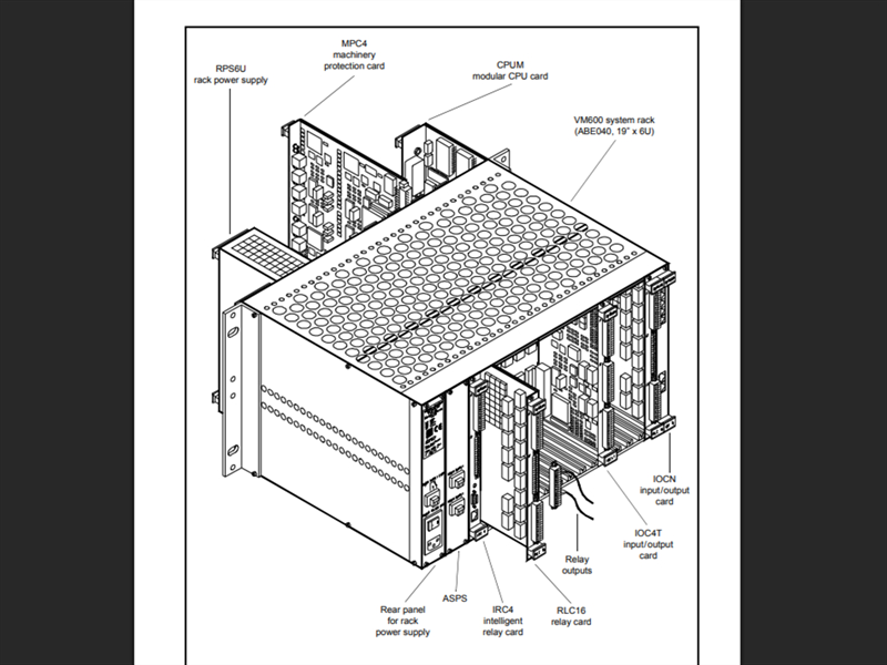
The VM600 series of machinery protection and condition monitoring systems from Meggitt’s Vibro-Meter® product line are based around a 19" rack containing various types of cards, depending on the application.
There are basically two types of system:
• VM600 machinery protection system (MPS – 1U or 6U rack).
• VM600 condition monitoring system (CMS – 1U or 6U rack).
It is also possible to integrate MPS and CMS hardware into the same VM600 rack (ABE04x).
In its most basic configuration, a VM600 machinery protection system (MPS) consists of the following hardware:
1- VM600 rack: 19" system rack x 6U (ABE04x) or 19" slimline rack x 1U (ABE056)
2- RPS6U rack power supply (ABE04x only)
When an AC-input version of the RPS6U is installed in a VM600 rack, the optional ASPS auxiliary sensor power supply can be used to replace external power supplies such as the APF19x 24 VDC power supplies.
3-
MPC4 machinery protection card
4-
IOC4T input/output card for the MPC4
5-
AMC8 analog monitoring card
6- IOC8T input/output card for the AMC8.
The MPC4 and IOC4T cards form an inseparable card pair and one cannot be used without the other. These cards are used primarily to monitor vibration for the purposes of machinery protection.
Similarly, the AMC8 and IOC8T cards form an inseparable card pair and one cannot be used without the other. These cards are used primarily to monitor quasi-static parameters such as temperature, fluid level or flow rate for the purposes of machinery protection
In general, a VM600 rack used for machinery protection can contain:
• Only MPC4 / IOC4T card pairs
• Only AMC8 / IOC8T card pairs
• A combination of MPC4 / IOC4T and AMC8 / IOC8T card pairs.
Depending on the application, the following type of cards can also be installed in the VM600 rack (ABE04x or ABE056):
7- RLC16 relay card (16 relays) and IRC4 intelligent relay card (eight relays combined as either 4 DPDT or 8 SPDT).
All the above items can be used to make a stand-alone MPS system, that is, one that is not connected to a network.
A networked version of the MPS will in addition contain the following hardware in the VM600
rack (ABE04x):
8- CPUM modular CPU card
9- IOCN input/output card for the CPUM.
Depending on the application (and irrespective of whether the rack is used in a stand-alone or a networked configuration), one or more of the following power supplies can be used outside a VM600 rack (ABE04x):
• APF19x 24 VDC power supplies
• Any equivalent low-noise power supply provided by the customer.
These devices must be used for GSI1xx galvanic separation units, GSV safety barriers and transducer and signal conditioner front-ends having a current requirement greater than 25 mA. They will often be mounted in the cubicle in which the rack is installed.
Card locations
The VM600 MPS rack (ABE04x) is a modular system with 21 card (VME) slots, designated slot 0 to slot 20 (from left to right, as seen from the front). See Figure 1-4.
The front and rear card cages of the rack are partitioned by a backplane. Each side of the back plane is equipped with connectors allowing modules and cards to be quickly and easily installed.
The following elements are connected to the backplane by installing them from the front of the rack:
• AMC8 analog monitoring card
•
CPUM modular CPU card
• MPC4 machinery protection card
•
RPS6U mains power supply unit
The following elements are connected to the backplane by installing them from the rear of the rack:
• IOC4T input/output card, for use with the corresponding MPC4
• IOC8T input/output card, for use with the corresponding AMC8
•
IOCN input/output card, for use with the corresponding CPUM
• IRC4 intelligent relay card
•
RLC16 relay card.
If the ABE04x rack is intended for use as a condition monitoring system (CMS) as well as an machinery protection system (MPS), it can contain additional hardware:
• XMx16/XIO16T extended monitoring card pairs.
 MPC4 machinery protection card
Figure 2-1 shows an MPC4 machinery protection card and describes the meaning of the card’s LEDs.
An MPC4 card has the following connectors:
• BNC connectors RAW OUT 1 to RAW OUT 4
• BNC connectors TACHO OUT 1 and TACHO OUT 2
• RS-232 connector.
An MPC4 card has the following front panel LEDs:
• One global DIAG/STATUS indicator for the MPC4 / IOC4T card pair
• Status indicators for the four measurement channels and the 2 rotational speed channels.
IOC4T input/output card
Figure 2-2 shows an IOC4T input/output card (required by MPC4 cards) both a) without mating connectors and b) when mating connectors are inserted. It also describes the meaning of the card’s LED.
An IOC4T card has three connectors: J1, J2 and J3 and a slot error indicator LED on the front panel.
AMC8 analog monitoring card
Figure 2-3 shows an AMC8 analog monitoring card and describes the meaning of the card’s LEDs.
An AMC8 card has an RS-232 connector.
An AMC8 card has the following front panel LEDs:
• One global DIAG/STATUS indicator for the AMC8 / IOC8T card pair
• Status indicators for the eight measurement channels.
IOC8T input/output card
Figure 2-4 shows an IOC8T input/output card (required by an AMC8 cards) and describes the meaning of the card’s LED.
An IOC8T card has four connectors: J1, J2, J3 and J4 and a slot error indicator LED on the front panel.
CPUM modular CPU card
Figure 2-5 shows the elements of an CPUM modular CPU card, describes their purpose and gives an enlarged view of the display.
A CPUM card has the following elements on its front panel:
• A display with potentiometer to adjust contrast
• RS-232 connector
• Ethernet connector
• Three status LEDs
• Diagnostic LED
• Slot selection buttons
• Alarm reset button.
IOCN input/output card
Figure 2-6 shows the elements of an IOCN input/output card (optional for CPUM cards) and describes their purpose.
An IOCN card has the following connectors:
• RS connector (type RJ11)
• Two serial communications connectors for the Modbus/RTU communication protocol (group A)
• Two serial communications connectors for the Modbus/RTU communication protocol (group B)
• Two Ethernet connectors.
Software configuration
The following procedure can be used to configure VM600 MPSx software after replacing a card:
1- Disconnect the front-end components (that is, transducer, signal conditioner, probe and cables) from the rack by unfastening the connectors on the IOC4T or IOC8T card installed in slot nn.
2- Insert into slot nn the MPC4 or AMC8 card whose configuration you want to read.
3- Use one of the VM600 MPSx software packages (MPS1 or MPS2) to read the configuration of the card in slot nn
(Communications > From MPC > Read Configuration).
See example in Figure 3-2, in which the card in slot 3 is selected.
4- Modify the card configuration if necessary using the VM600 MPSx software.
5- Use one of the VM600 MPSx software packages (MPS1 or MPS2) to send the (modified) configuration to the card in slot nn
(Communications > To MPC > Send Configuration).
6- Reconnect the front-end components to the connectors on the IOC4T or IOC8T card installed in slot nn.