The information in this document applies to the overall Mark* VIe control system or Mark VIeS Functional Safety System control products; however, your application may not be licensed to access full system capability and I/O packs as described in this document. For example, the Mark VIeS Functional Safety System for General Markets only utilizes the following I/O packs:
• Analog I/O (YAIC)--IS420YAICS1B
• Universal Analog (YUAA)--IS420PUAAH1A
• Vibration Input Monitor (YVIB)--IS220YVIBS1A
• Relay Output (YDOA)--IS420YDOAS1B
• Discrete Contact Input (YDIA)--IS420YDIAS1B
• Power Distribution System Diagnostics (PPDA)--IS220PPDAH1A
• Serial Modbus Communication (PSCA)--IS220PSCAH1A
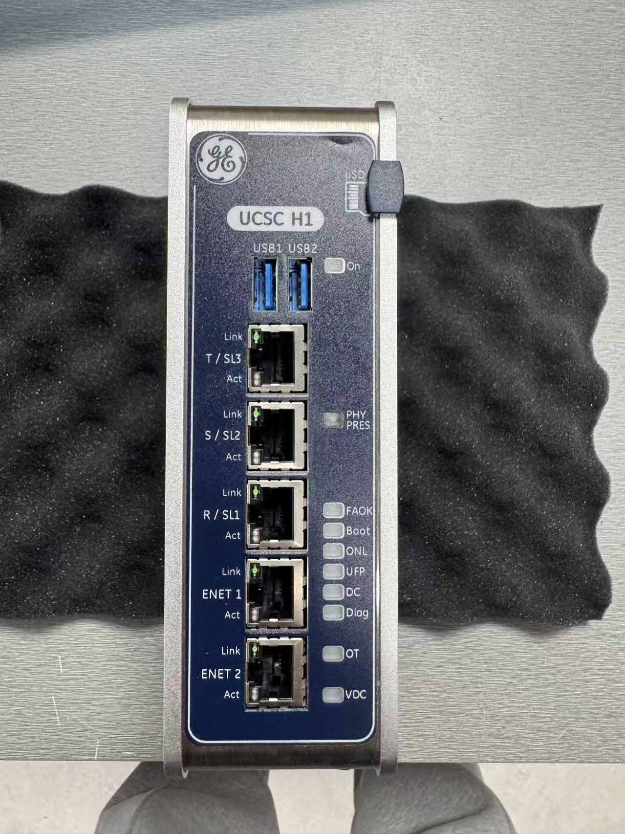
• Mark VIeS Safety Controller (UCSCS2x)--IS420UCSCS2A
• Mark VIe Controller for Gateway (UCSCH1x)--IS420UCSCH1B
1.2 Controllers
The Mark VIe controller is a stand-alone, single-board controller with scalable processing power. It includes built-in power supplies and requires no batteries or jumper settings. Controllers run the ControlST* Software Suite, providing a common software environment for turbine and generator excitation controls in the power island and balance of plant equipment to simplify operations and maintenance.
The Mark VIeS Safety controller is IEC 61508 certified to SIL 3.
Controllers are loaded with software specific to its application, such as steam, gas, land-marine (LM), Balance of Plant (BoP), offshore drilling, desalination, CS, and Wind Power Conversion. It can run Relay Ladder Diagrams (RLD) or blocks. The IEEE® 1588 protocol is used through the R, S, and T I/O networks (IONet) to synchronize the clock of the I/O modules and controllers to within ±100 microseconds. Data is transferred to and from the control system database in the controller over the I/O networks (IONet). IONet data includes process inputs/outputs to the I/O packs.
In a dual system, IONet data also includes:
• Internal state values and initialization information from the designated controller
• Status and synchronization information from both controllers In a triple module redundant (TMR) system, IONet data also includes:
• Internal state values for voting and status and synchronization information from all three controllers
• Initialization information from the designated controller
1.3 IONet Switches
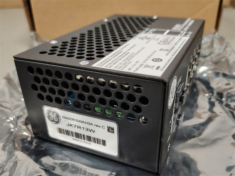
GE Vernova’s Industrial Ethernet 10/100 switches (ESWA and ESWB) provide the performance and features needed in today’s real-time industrial control systems. Use 8-port ESWA or 16-port ESWB Ethernet switches in all control system I/O networks to maintain the reliability needed for I/O module reception of controller outputs.
1.4 Distributed I/O Modules
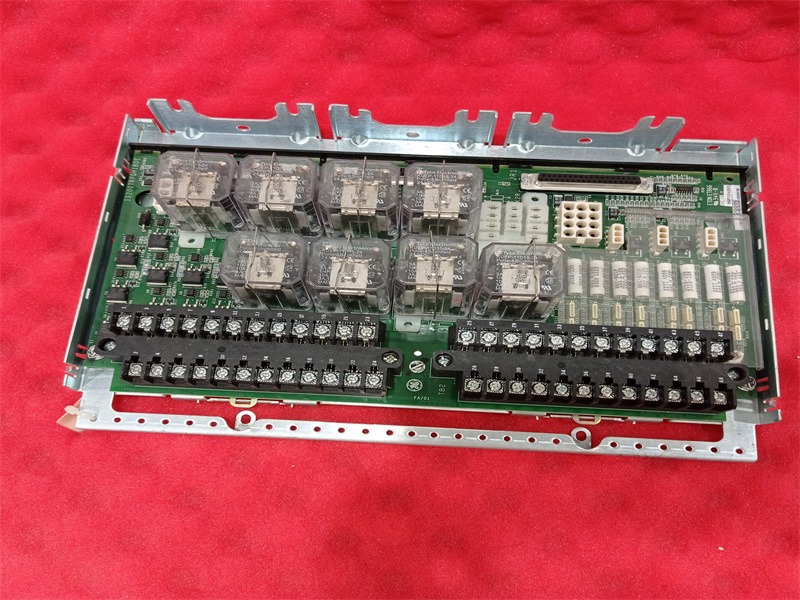
The I/O modules contain three basic parts: terminal board, terminal block, and I/O pack. The terminal board mounts to the cabinet and comes in two basic types: S and T. The I/O pack mounts to the terminal board J-port connector. Both terminal board types provide the following features:
• Terminal blocks for I/O wiring
• Mounting hardware
• Input isolation and protection
• I/O pack connectors
• Unique electronic ID
1.4.1 I/O Packs
I/O packs have a common processor board and a data acquisition board that is unique to the type of connected device. I/O packs on each terminal board digitize the I/O variables, perform algorithms, and communicate with the controller.
The I/O pack provides fault detection through a combination of special circuitry in the data acquisition board and software running in the Central Processing Unit (CPU) board. The fault status is transmitted to and used by the controllers. The I/O pack transmits inputs and receives outputs on both network interfaces if connected.
Each I/O pack also sends an identification message (ID packet) to the main controller when requested. The packet contains, the hardware catalog number of the I/O board, the hardware revision, the board barcode serial number, the firmware catalog number, and the firmware version. The I/O packs have a temperature sensor that is accurate to within ±2 °C (±3.6 °F). Every I/O pack temperature is available in the database and can be used to generate an alarm.
1.4.2.1 T-type
T-type terminal boards typically fan the sensor inputs to three separate I/O packs. Usually, the TMR board hardware votes the outputs from the three I/O packs. T-type boards contain two, 24-point, barrier-type, removable, terminal blocks. Each point can accept two 3.0 mm (0.12 in) (#12 AWG) wires with 300 V insulation per point with either spade or ring-type lugs. In addition, captive clamps are provided for terminating bare wires. Screw spacing is 9.53 mm (0.375 in) minimum and center-to-center.
These terminal blocks have the following features:
• Black in color with white number labels
• Terminal rating is 300 V, 10 A
• UL recognized
• Recommended screw tightening torque is 7 lb-in (0.8 Nm).
For more information,please contact with colletplc.com.
Address : Unit 1904, No.96-2 Lujiang Road, Siming District, Xiamen
Phone/WhatsApp/Skype : +86 18060982349
E-mail : sales6@nseauto.com