Introduction
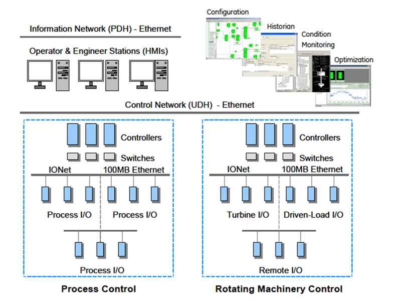
Mark* VIe is a flexible control system for multiple applications. It features highspeed, networked I/O for simplex, dual, and triple redundant systems. Industrystandard Ethernet communications are used for I/O, controllers, and supervisory interface to operator and maintenance stations, and third-party systems.
ToolboxST* is used for Mark VIe and related controls as a common software platform for programming, configuring I/O, trending, and analyzing diagnostics. It provides a single source of quality, time-coherent data at the controller and plant level for effectively managing equipment assets.
Architecture
A single-board controller is the heart of the system. It includes the main processor and redundant Ethernet drivers for communicating with networked I/O and additional Ethernet drivers for the control network. A QNX® real-time, multitasking operating system is used for the main processor and I/O. Application software is provided in a configurable control block language, and is stored in non-volatile memory. It conforms to IEEE-854 32-bit floating-point format.
IONet is a dedicated, full-duplex, point-to-point protocol that provides a deterministic, high-speed 100 MB communications network suitable for local or remote I/O with a fiber interface. It provides communication between the main processor(s) and networked I/O blocks, called I/O packs.
Each I/O pack is mounted on a board with barrier or box-type terminal blocks. The I/O pack contains two Ethernet ports, a power supply, a local processor, and a data acquisition board. Computation power grows as I/O packs are added to the control system, enabling an overall control system frame rate of 10 ms in simplex, dual, or triple redundant configuration. Some process sub-systems require even more performance; therefore, the local processors in each I/O pack run algorithms at higher rates as required for the application.
I/O Interface
One or multiple I/O packs are mounted on each board to digitize the sensor signal, perform algorithms, and communicate with a separate controller that contains the main processor. I/O packs have a local processor board that runs a QNX operating system and a data acquisition board that is unique to the type of input device. Local processors run algorithms at faster speeds than the overall control system.
An infrared transceiver is useful for low-level diagnostics. I/O values can be monitored, I/O pack host/function names can be programmed, and error statuses can be checked. This requires a Windows®-based diagnostic tool on a laptop or a handheld computer.

• Dual 100 MB Ethernet ports
• 100 MB full duplex ports
• Online repair per I/O pack
• Operation -30°C to 65°C (-22 °F to 149 °F)
• Accuracy -30°C to 65°C (-22 °F to 149 °F)
• I/O packs rated Class 1, Div. 2
• Ambient temperature sensor
• LEDs: power status and attention
• LEDs: Ethernet link-connected and communication-active
• LEDs: application-specific
• Processor: 32-bit RISC CPU 266 mHz
• Infrared Transceiver: Low level diagnostics, monitor I/O, set host/function names, error status
• Power: 28 V dc (typical)
• Internal solid-state circuit breaker and soft start
The I/O Processor contains a temperature sensor that is accurate to within ±2°C (±3.6 °F). Detection of an excessive temperature generates a diagnostic alarm, and the logic is available in the database (signal space) to facilitate additional control action or unique process alarm messages. In addition, the temperature is continuously available in the database.
A power supply provides a regulated 28 V dc power feed to each I/O pack. The negative side of the 28 V dc is grounded through the I/O pack metal enclosure and its mounting base. The positive side has solid-state circuit protection built-into the I/O pack with a nominal 2 A trip point. Online repair is possible by removing the 28 V dc connector, replacing the I/O pack, reinserting the power connector, and downloading software from the software maintenance tools.
Terminal Blocks
Signal flow begins with a sensor connected to a terminal block on a board. There are two types of boards available. T-type boards contain two 24 point, barrier-type, removable, terminal blocks. Each point can accept two 3.0 mm2 (#12AWG) wires with 300 V insulation per point with spade or ring type lugs. In addition, captive clamps are provided for terminating bare wires. Screw spacing is 9.53 mm (0.375 inch) minimum, center-to-center.
A shield strip is provided next to each block, which is actually the left-hand side of the metal base where the board is mounted. Wide and narrow boards are arranged in vertical columns of high and low-level wiring that can be accessed from top and/or bottom cable entrances. An example of a wide board is a board that contains magnetic relays with fused circuits for solenoid drivers. T-type boards are normally surface mounted, but can also be DIN-rail mounted.
S-type boards have one I/O pack for simplex and dual redundant systems. They are half the size of T-type boards and are DIN-rail or surface mounted. Two versions of the boards are available, H1 and H3. H1 boards have fixed terminal blocks, and H3 boards have removable terminal blocks. A H2 version is available for mounting of custom blocks such as spring-cage or insulation displacement.
S-type boards have box type terminal blocks that accept one 3.0 mm2 (#12AWG) wire or two 2.0 mm2 (#14AWG) wires with 300 V insulation per point. Screw spacing is 5.08 mm (0.2 inch) minimum, center-to-center. A shield strip is provided to the left of each block. It can be connected to a metal base for immediate grounding or floated to allow individual ground wires from each board to be wired to a centralized, cabinet ground strip.

|
I/O Type - General Purpose |
Board |
Redundant Packs/Boards |
|
24 DI (125 V dc, group isolated) 1 ms SOE |
IS200TBCIH1 |
1 or 2 or 3 |
|
24 DI (24 V dc, group isolated) 1 ms SOE |
IS200TBCIH2 |
1 or 2 or 3 |
|
24 DI (48 V dc, group isolated) 1 ms SOE |
IS200TBCIH3 |
1 or 2 or 3 |
|
24 DI (115/230 V ac, 125 V dc, point isolated) 1 ms SOE on 125 V dc |
IS200TBCIH1 |
1 or 2 or 3 |
|
24 DI (24 V dc, point isolated) |
IS200TBCIH2 |
1 or 2 or 3 |
|
24 DI (24 V dc, group isolated) |
IS200STCIH1 |
1 |
|
12 C mechanical relays w/6 solenoids, coil diagnostics (115/230 V ac, 24/125 V dc) |
IS200TRLYH1B |
1 or 3 |
|
12 C mechanical relays w/6 solenoids, voltage diagnostics (115/230 V ac, 125 V dc) |
IS200TRLYH1C |
1 or 3 |
|
12 C mechanical relays w/6 solenoids, voltage diagnostics (24 V dc) |
IS200TRLYH2C |
|
|
6 A mechanical relays for solenoids, solenoid impedance diagn. (24/125 V dc) |
IS200TRLYH1D |
1 or 3 |
|
12 A solid-state relays/inputs (115/230 V ac) |
IS200TRLYH1E |
1 or 3 |
|
12 A solid-state relays/inputs (125 V dc) |
IS200TRLYH2E |
1 or 3 |
|
12 A solid-state relays/inputs (24 V dc) |
IS200TRLYH3E |
1 or 3 |
|
36 mechanical relays, 12 voted form A outputs |
IS200TRLYH1F |
3 |
|
12 fused branches |
IS200WPDFH1A |
|
|
36 mechanical relays, 12 voted form B outputs |
IS200TRLYH2F |
3 |
|
12 fused branches |
IS200WPDFH2A |
|
|
10 AI (V/I inputs) and (2AO (4-20/0-200 mA outputs) |
IS200TBAIH1C |
1 or 2 or 3 |
|
10 AI (V/I inputs) and (2AO (4-20/0-200 mA outputs) |
IS200STAIH1A |
1 or 2 or 3 |
|
16 AO (4-20 mA outputs) 8 per I/O pack |
IS200TBAOH1C |
1 or 2 |
|
8 AO (4-20 mA outputs) |
IS200STAOH1A |
1 |
|
12 thermocouples |
IS200TBTCH1B |
1 or 2 or 3 |
|
24 thermocouples (12 per I/O pack) |
IS200TBTCH1C |
1 or 2 |
|
12 thermocouples |
IS200STTCH1A |
1 |
|
16 RTDs 3 wires/RTD (8 per I/O pack) |
IS200TRTDH1C |
1 or 2 |
|
8 RTDs 3 wires/RTD |
IS200SRTDH1A |
1 |
|
6 serial ports for I/O drivers RS-232, RS422, RS485 |
IS200SSCAH1A |
1 |
|
10/2 analog I/O - HART communications |
IS200SHRAH1A |
1 |
|
PROFIBus communications |
IS200SPIDH1A |
1 |
|
I/O Type - Turbine |
Board |
Redundant Packs/Boards |
|
Mixed I/O: 4 speed inputs/pack, synchronizing, shaft V/I monitor |
IS200TTURH1C |
1 or 3 |
|
2 servo channels: up to 3 coils, 4 LVDTs/channel, includes excitation |
IS200TSVCH1A |
1 or 3 |
|
8 vibration (seismic, proximity, accel.), 4 position, 1 reference probe, buffered out |
IS200TVBAH1A |
1 or 2 or 3 |
I/O Types
General purpose I/O is used for both turbine applications and process control.Turbine-specific I/O is used for direct interface to the unique sensors and actuators on turbines. This reduces or eliminates a substantial amount of interposing instrumentation. As a result, many potential single point failures are eliminated in the most critical area for improved running reliability and reduced long-term maintenance. Direct interface to the sensors and actuators also enables the diagnostics to directly interrogate the devices on the equipment for maximum effectiveness. This data is used to analyze device and system performance. Also, fewer spare parts are needed.
Address : Unit 1904, No.96-2 Lujiang Road, Siming District, Xiamen
Phone/WhatsApp/Skype : +86 18060982349
E-mail : sales6@nseauto.com